
**EDIT May 2018** A new 4-axes motion controller! I upgraded my earlier version of the controller to this 4-axes motionPro 6600 controller. It integrates four 4A Toshiba drivers, works with LinuxCNC and Mach3/4 and pretty much any other software. Its being crowdfunded now on Crowd Supply.
*--*--*
Please note that the printed parts shown in the images here are a couple of versions older and I've updated the models in the parts list. Mainly, I've widened the gantries towards the rail side for added stability. I've also added space on them for attaching the micro limit switches.
Here is how the finished assembly modelled in Fusion 360 looks like. On the page, click on 'Explode Model' to see how each axis and frame is assembled.
I started off by assembling the Y-axis motor mounts. I first assembled the 4 M5x30mm screws followed by eccentric spacers on the bottom two screws and 1/4 in aluminium spacers on the top two screws. Even though the eccentric spacers have grooves on them I marked them with a permanent marker just to make it more visually accessible.
Though I've not put any shims between the eccentric spacers and the wheels in the model that I built, it is recommended that you do. The 3D model also shows aluminium spacers at the end of the screw which are optional. If your M5 nut is smaller than the wheel then this spacer is not necessary since the nut will not obstruct motion on the rails. The last step is fixing the stepper motors using M3x10mm screws. The GT pulley will go on the motor shafts after this. Note that the pulley width needs to be aligned with the width of the wheel to ensure the belts are straight on the rails.
The finished Y-axis assemble for one side. I had initially used two M5 nuts at the screw ends but eventually I removed one of them since I didn't quite think they were necessary. You could also use a shorter screw length.
After you've built the second side of the Y-axis, you'll need to link the two sides using the 2020 V-slot. However, before you do this, you'll need to insert a single M5 T-nut on either side. These essentially help you screw down the endstops in place. This is important since if you do not do this, you'll need to disassemble the two sides, add the nuts and then reassemble which I'm sure would be quite a painful and tedious. Secure the X-axis 2020 between the two Y-axis gantries with a M5 10mm screw on either side.
Next you'll want to slide the Y-axis rails and slowly turn the eccentric spacers inwards to snug the wheels on to the rails. Do not make them too snug. I follow a simple rule: while holding the rails if you can turn the wheels with some effort then you've snugged it right.
The X carriage plate is done the same way. Here the rail hugging assembly lies between the motor and the laser mount.
The End-stops
This design has end-stops that combines the functionality of holding the GT belt in place and acting as stops for the limit switches at the same time. Also since the Y-axis mounts are essentially the same part, you can mount the limit switches on any side thereby reducing wire length for the Y-axis. These end-stops are common across the X and Y axes and are connected exactly the same way across both.
I've added another version from my previous build however, the new version is included in the files.
I've added two switches in NC for homing. The full configuration is available for download in the files. This configuration homes in the top right corner and sets the coordinate space in the positive.
The key to getting homing right is to get the right combination of step direction of the axis ($3), homing direction ($23) and limit pins invert option ($5. For NC this is 1 and for NO switches this is 0).
A video of the setup homing
The Laser
I bought my laser from DTR. I blew out one laser during testing and got a different model the next time. This particular model becomes a very expensive LED when the current limit is exceeded but goes back to lasing when the current is within limits again. Make sure you get them in a copper housing with a 2-element lens and the 12mm Aixiz mount. This also comes in a 3-element glass which is cheaper but not recommended since there is significant loss in power transfer. I also got a heatsink with a fan and attached the laser mount to this using M3 screws. If you are going the same route to assembling your laser, I suggest adding two M3 washers between the heatsink and the X-axis mount plate. This is because the fan on the heatsink sits slightly higher than the top edge and the washers allow the requisite clearance.
The finished laser assembly is shown below.
The Frame
Once you've made sure there is no play between the rails and wheels, its time to square everything and put it together. Though the design suggests the use of 2040 rails parallel to the X-axis 2020 extrusion, I didn't have any so I used regular 2in x 1in hollow aluminium bars and these worked out just as great and they were cheaper as well.
I used corner brackets to align and join the extrusions at right angle. Some might differ with this approach with the argument that there might be play in them at a later stage. However, they seem very nice and tight without any loose couplings. Note that these brackets come with ridges on either side since they are meant to hold two extrusions perpendicular to each other with their slots aligned. Which is why I had to file off the ridges for one side. For the moment they seem to hold good. Use M5 6mm low profile screws to secure the end brackets.
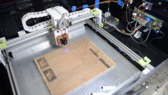
'Scout' tests wire integrity and verifies that everything is squared up.
The finished assembly.
Note that the entire system sits on an 1.5mm aluminium sheet screwed to a 12mm sheet of plywood underneath it. This makes it somewhat heavy. The assembly shows end-stops from Much 4's build since I already had them from an earlier version and didn't want to print them again in the interest of saving cost.
Another part that I borrowed from my earlier build is the cable clips that hold the motor and laser wires along the X-axis. However, I designed another part for this and that is attached in the part files.
The Electronics
Since commercial laser drivers are very expensive, I eventually designed my own. The laser driver is essentially a constant current LED driver capable of driving upto 1A at about 5V. The gerbers and schematic are attached in the parts list.
The motor drivers is essentially a grbl based system that uses a regular Arduino with driver carriers such as the DRV8825 to make a complete motion system. Initially I had pieced this together from bits and pieces but I eventually made my own board with a few more options such as wireless control. This board is available for sale on Tindie as well [and my apologies for the shameless self-promotion].
The grbl Wiki is a great place to start when it comes to motor settings, resolution etc. I also found the Prusa printers excellent online calculator for calculating the number of steps/mm etc.
Possible future enhancements
This build in action
- I'll probably design a better X-axis laser mount that allows for some manual Z-axis adjustment as well.
- Replace the cable clips with a drag chain.
- I accidentally bought dual shaft motors since they were cheaper and eventually I'll replace them with single shaft ones though this has not affected build performance in any way.
- A more high powered laser. The current one I'm using is 1.6W and I'll eventually upgrade to a 5W laser.
- Use hall effect limit switches.
- Possible convert this from a belt design to a lead screw based design.
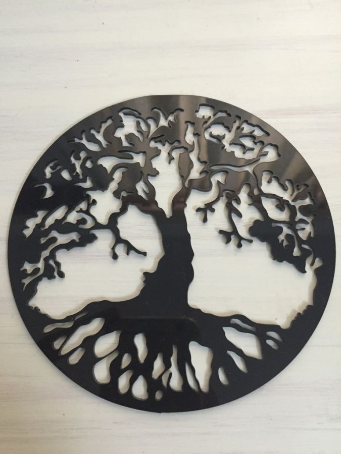
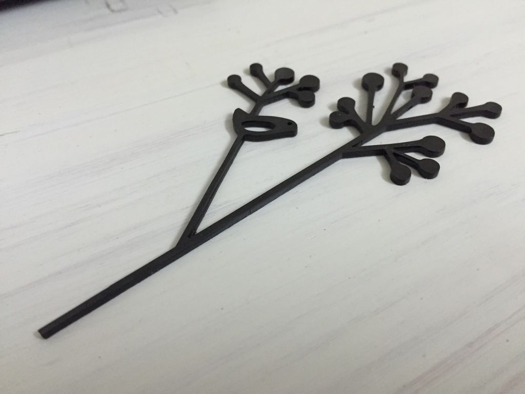
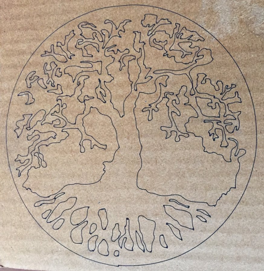
A few samples from what I've engraved/cut with this build. The plastic took several passes but came out nice and clean.
A simple XY laser engraver/cutter
Build in 'Laser Cutter Builds' published by HPB, May 31, 2018.
A simple low-cost XY plane laser engraver/cutter inspired by the Much 4 laser build, with minimal parts and assembly time. Uses standard off the shelf components in almost 90% of the build with the exception of the axes motor and wheel mounts which need to be 3D printed.
-
-
Build Author HPB, Find all builds by HPB
-
- Loading...
-
Build Details
- Build License:
-
- CC - Attribution NonCommercial - Share Alike - CC BY NC SA
Reason for this Build
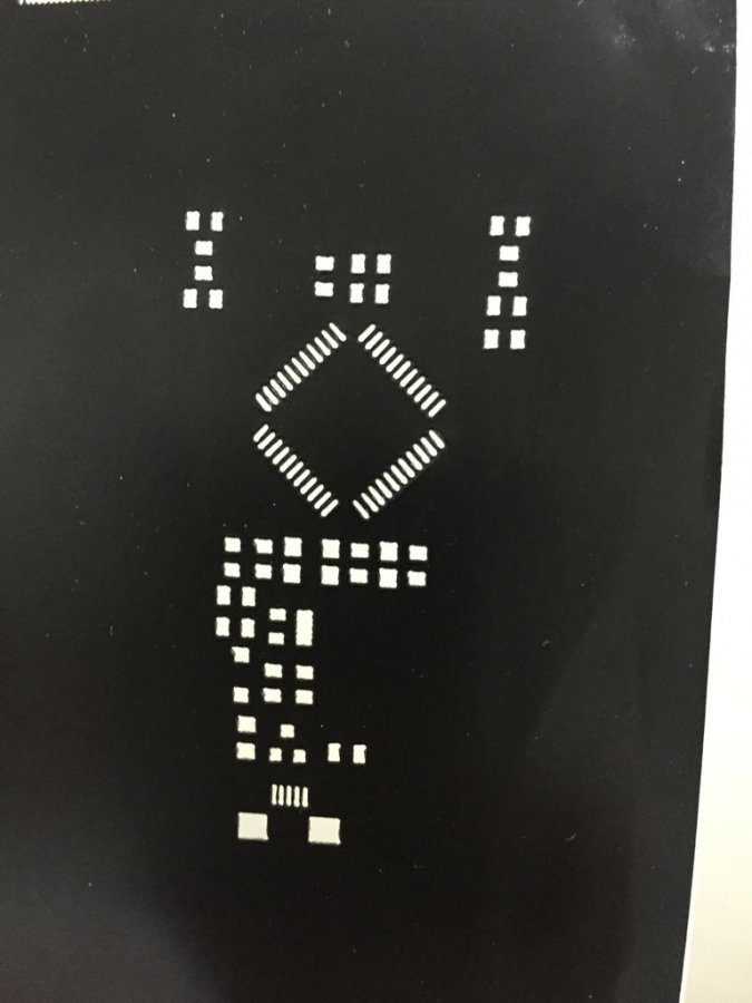
I tinker with a lot of electronics and most PCBs contain SMD parts. To solder them you need stencils for the paste dispersal and these are usually made of aluminium and are quite expensive. I built this to create stencils from more common materials such as plastic and mylar sheets.Inspired by
Inspired by Much 4 laser build (Much4 - LaserV printed version) -
Attached Files:
Parts list
Qty Part Name Part Link Comments 3 V-Slot 20mmx20mmx500mm http://openbuildspartstore.com/v-slot-linear-rail/ Link 2 V-Slot 20mmx40mmx500mm http://openbuildspartstore.com/v-slot-linear-rail/ Link To reduce cost further you could use a 2020 V-slot here as well. However to ensure that the laser is seated at a height from the main bed, you will need to use rectangle/square aluminium tubing. 12 Mini V Wheels (assembled) http://openbuildspartstore.com/delrin-mini-v-wheel-kit/ Link The usually come assembled with two bearings, a wheel and a precision shim seperating the bearings. 6 Eccentric spacers http://openbuildspartstore.com/eccentric-spacer/ Link Two on each gantry towards the bottom edge 6 Aluminium spacers 0.25in http://openbuildspartstore.com/aluminum-spacers/ Link 24 Precision 1mm shims http://openbuildspartstore.com/mini-v-wheel-precision-shim/ Link The image shows only one shim between the V wheel and the nut but another one is recommended between the spacer and the V wheel 12 M5 x 30mm low profile screws http://openbuildspartstore.com/low-profile-screws-m5/ Link 2 M5 x 10mm low profile screws http://openbuildspartstore.com/low-profile-screws-m5/ Link To secure the X-axis V-slot to the Y gantries. These can also be used to secure the endstops and corner brackets to the frame. Button head screws would work too. 12 M5 nut http://www.ebay.com/sch/i.html?_from=R40&_trksid=... Link Pack of 25 12 M3 x 10mm http://www.ebay.com/itm/Metric-M3-M4-Black-10-9-Alloy-Ste... Link For attaching the motors to the gantry. Pack of 20. 4 M3 x 30mm http://www.ebay.com/itm/Metric-M3-M4-Black-10-9-Alloy-Ste... Link For attaching the heatsink to the X-gantry. Pack of 20. 3 M3 x 6mm http://openbuildspartstore.com/button-head-screws-m3-25-p... Link For attaching the Aixiz laser mount to the heatsink. Pack of 25. 3 NEMA 17 stepper motors single shaft http://openbuildspartstore.com/nema-17-stepper-motor/ Link 3 GT pulley 20 tooth 2mm pitch 5mm bore http://openbuildspartstore.com/gt2-2mm-timing-pulley-20-t... Link 3 GT 2mm pitch 6mm wide timing belt ( in meters) http://www.ebay.com/itm/2m-2GT-6mm-Rubber-Pulley-Timing-B... Link Pack of 4 4 Microswitches http://www.ebay.com/itm/10Pcs-KW12-3-Micro-Roller-Lever-A... Link Limit switches 4 Cast corner brackets http://openbuildspartstore.com/cast-corner-bracket/ Link You could use 4 more to attach them on the bottom of the 2020 rails too for added rigidity. 14 Tee nuts http://openbuildspartstore.com/tee-nuts-25-pack/ Link 1 Laser diode 1.6W https://www.amazon.com/gp/product/B00I6SD6AY/ref=oh_aui_d... Link 1 Heatsink with fan for the laser 55mm http://www.ebay.com/sch/sis.html?_nkw=GEB+-+281828972352+... Link This was a peculiar find but it was really healpful since it enabled attaching the Aixiz laser module to it very neatly 1 Aixiz 12mm x 30mm laser mount https://www.amazon.com/AixiZ-aluminum-mount-heat-modules/... Link 1 Safety goggle https://www.amazon.com/gp/product/B0050YOOA8/ Link Must have! 0 Link -
Attached Files:
![[IMG]](proxy.php?image=http%3A%2F%2Fi.imgur.com%2FBdXbKAN.jpg&hash=0f3bdf48a24ccb8c968183f2a9d3c38a)
![[IMG]](proxy.php?image=http%3A%2F%2Fi.imgur.com%2F4PbjdeA.jpg&hash=714a36ea4b11fb4ae5f2f2849c280656)
![[IMG]](proxy.php?image=http%3A%2F%2Fi.imgur.com%2FcazGIDP.jpg&hash=3ba8e649a110a12ac1205fc0fc0969c3)
![[IMG]](proxy.php?image=http%3A%2F%2Fi.imgur.com%2F81oVjYE.jpg&hash=66a80d39c171964be9ad7edc99549b3b)
![[IMG]](proxy.php?image=http%3A%2F%2Fi.imgur.com%2FKh8Q2dg.jpg&hash=cff82fe99921c3cfe35c9708db3947d8)
![[IMG]](proxy.php?image=http%3A%2F%2Fi.imgur.com%2FbLAcqJe.jpg&hash=f81a004796dfaca1b33e6c7e5ace3a9d)