
About the build
This build is for an all metal 3D printer that utilises OpenBuilds V-Slot linear rails and custom aluminium plates to create a high quality and cost effective 3D printer. I designed the printer with the following goals:
Latest Progress
- Use a minimal number of parts without compromising frame rigidity.
- Be scalable printer for your desired build area.
- Use remote hotends with a standard 16mm groove mount such as the E3D V6.
- Build cost less than £400 (~$570)
So far I have completed building most of the mechanical structure including frame and XYZ-axis assembles. The next stage is to mount the limit switches, wire up the electronics and build an electronics enclosure.

When I have time I will upload step by step assembly instructions and more info about the build. Once the build is completed and tested I will upload: CAD files for the custom plates including 200*200 mm, 200*300 mm and 300*300 mm build plates; CAD 3D printer assembly; and a bill of materials.
Assembly
The version of the printer I am building has 360mm and 340mm of travel for the X and Y axis respectively, and the Z-axis has 360mm of travel. I will be using a 300*200 mm build plate and leaving room to upgrade to a 300*300 mm plate at a later date.
Step 1 - Machine the custom plates
I milled the plates out of 3mm thick aluminium, however the large build plate was milled from 4mm thick aluminium for extra rigidity. If you don't have access to a CNC machine you would be surprised how inexpressive it is for your local machine shop to make the plates for you especially with this simple design.

Step 2 - Mount the V Wheels
I used Delrin V Wheels although you could use any of the full sized OpenBuilds wheels.

Step 3 - Assemble the base frame
Attach the two 60*20 V-Slot base beams to the 40*20 V-Slot Y-axis rail using 4 cast corner brackets and cross joining plate. Two T joining plates should be mounted on either end of the 60*20 V Slot base beams for mounting the top frame assembly in the next step. I used four 10mm thick rubber feet with M5 mounting holes to form a level base for the printer.


Step 4 - Assemble to the top frame
Attach the two 20*40 V Slot Z-axis rails to the base assembly using 5 cast corner brackets and a T joining plate for each of the two rails. Attach the top 20*20 V Slot beam to the two 20*40 V Slot Z-axis rails using a cast corner bracket and a 90 degree joining plate. Remember to slide on the two Z-axis carriages before attaching the top beam.

Step 5- Assemble the X-axis
Side on the X-axis carriage assembly onto the 20*40 V Slot X-axis rail then attach the rail to the two Z-axis carriages.

Step 6 - Assemble the Y-axis
First slide the build plate assembly onto the 20*40 V Slot Y axis rail then attach the Y-axis motor mount plate and Y-axis idler pulley plate to the ends of the rail.

Step 7 -Attach the Z-axis motor mount plates
Attach the two Z-motor mount plates onto the the top frame assembly.

Step 8 - Attach the stepper motors
Attach the 4 stepper motors and the 30 tooth GT2 timing pulleys to the X and Y axis motors.

Step 9 - Install the timing belts
Install the GT2 timing belts for the X and Y axis, use cable ties to secure the belts. Installing belt tensioners ensure the belts are tight.


Step 10 - Install the lead screw assemblies
Install a lead screw assemblies including a 8mm-5mm flexible shaft coupler, 400mm lead screw and anti-backlash nut block to each of two the Z-axis.


Step 11 - Mount the hotend, extruder and heated bed
The all metal hotend was mounted using a standard groove mount plate and the metal bowden extruder was mounted to the 20*20 V Slot to beam with M3 screws and T-nuts. The 200*300 aluminium mk2a heated bed was attached to the build plate assembly using a spring loaded M3 bed levelling kit. A sheet of Borosilicate glass is clamped onto the heated bed using bulldog clips.


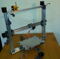
Archer - An extendable all metal 3D printer
Build in 'Cartesian Style Bots' published by James Archer, Jul 15, 2016.
This is an all metal build using OpenBuilds V-Slot linear rails to produce a high quality and cost effective 3D printer. The printer is designed to be scalable for your desired build area and can utilize high quality hotends with 16mm groove mounts such as E3D.
-
-
Build Author James Archer, Find all builds by James Archer
-
- Loading...
-
Build Details
- Build License:
-
- CC - Attribution NonCommercial - Share Alike - CC BY NC SA
Reason for this Build
I wanted good quality 3D printer with a large build volume but I didn't want to spend more than £400. I couldn't find any printers on the market at my price point and I have wanted to build an v-slot printer for a while thus I started work on the Archer printer.Inspired by
TEVO Tarantula I3


