
So, this is my latest build for a client. Kind of interesting, he wants a machine to punch Braille dots onto clear vacuum/heat formed signs for things like Toilets, Office numbers, etc. for public buildings. He makes cutouts for the letters and symbols, and sticks them on the back of a piece of clear plastic. Then he vacuum/heat forms the clear plastic down over the foam cutouts to make a raised symbol or text. Then, he manually punches Braille dots under the text using a template with holes drilled for the braille characters. Kind of digressing here, but it's an interesting application.
This machine will both be able to drill the templates in whatever size he wants, and automate the punching process by using a blunt punch chucked into the router. Had a friend of mine whip up some custom software to generate the g-code to do the drilling and punching.
Anyway, on to the build. This is pretty much a stock C-Beam XL, with a few modifications. Seems I can't build anything without putting my own stank on it.
I changed a few things about the machine design I didn't like. #1 was I used a 40x40 as the brace between the 2 C-Beam uprights instead of a 20x40. Just though it would add a bit of strength. Sorry this turned out a bit dark. This is why I'm not a photographer. The 40x40 is in the foreground.
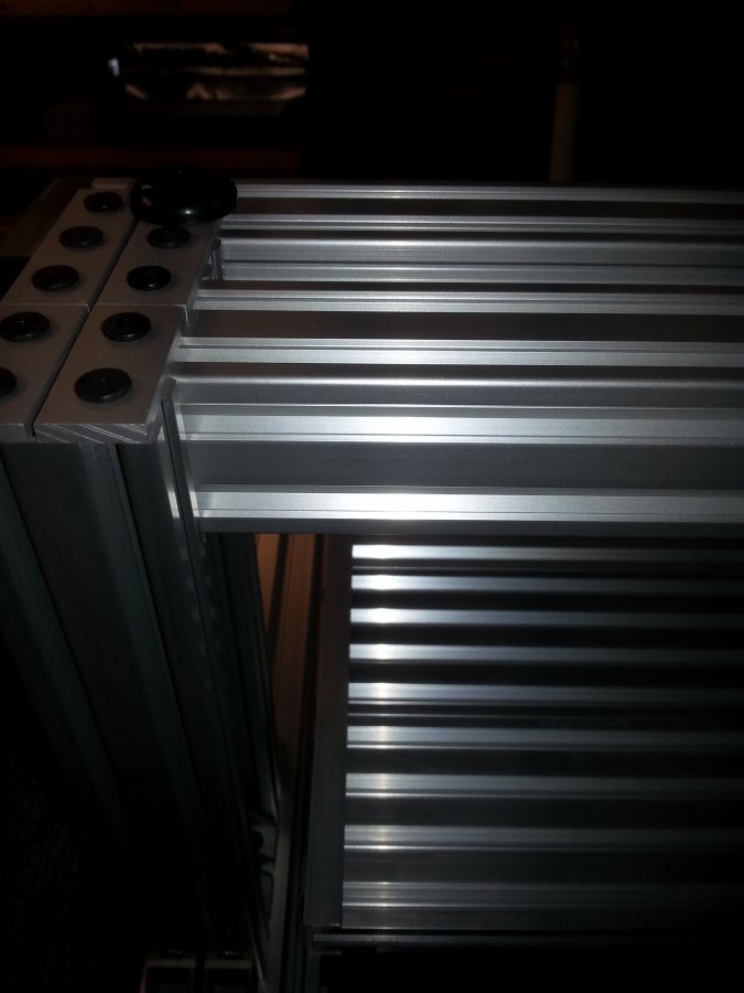
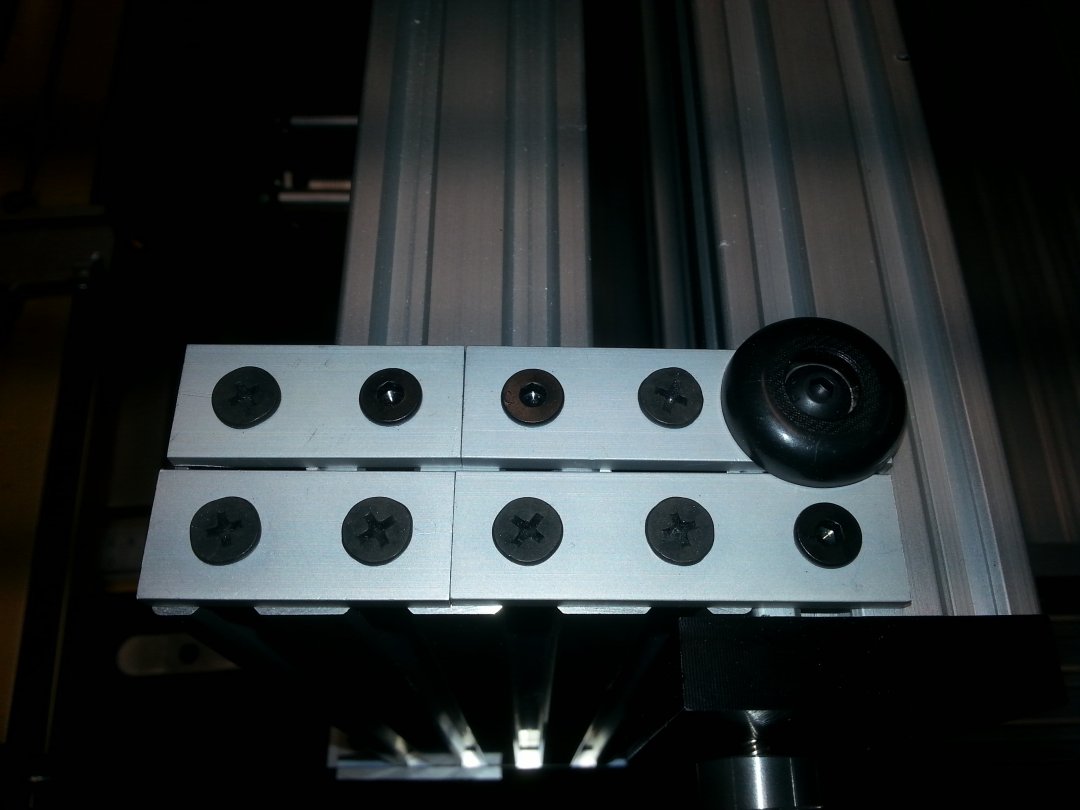
I also changed one of my pet peeves with the C-Beam machines, both the original and this one. Those dang 5 hole corner brackets are wheel killers. The corner sticking out on the top of the c-beam has a sharp edge that will ding up or even crack your wheels if you run into it, which you are bound to do sooner or later. It also reduces your X travel by 40mm. So, I came up with a fix using stock parts. The C-beam is held on by two 3-hole straight brackets, which sit with the middle hole on the top of the upright c-beam. This allows it to straddle the upright, and attach to both the x-axis C-beam and the 40x40 with tee nuts. I just used a self tapping screw in the center cuz I hate threading. One of these days I'll design a full 120x40mm 6x2 hole plate to do this all with one custom bracket
I put a couple of 2 hole joiner plates on the back side which cover up the cut end of the c-beam and attach the back slot of the 40x40 to the upright as well. These tricks gained me 40mm of X travel. Also, note the soft rubber bumper to protect the wheel from contacting the joiner plate.
I only made this machine 800mm wide instead of 1000, because that's all that was needed.
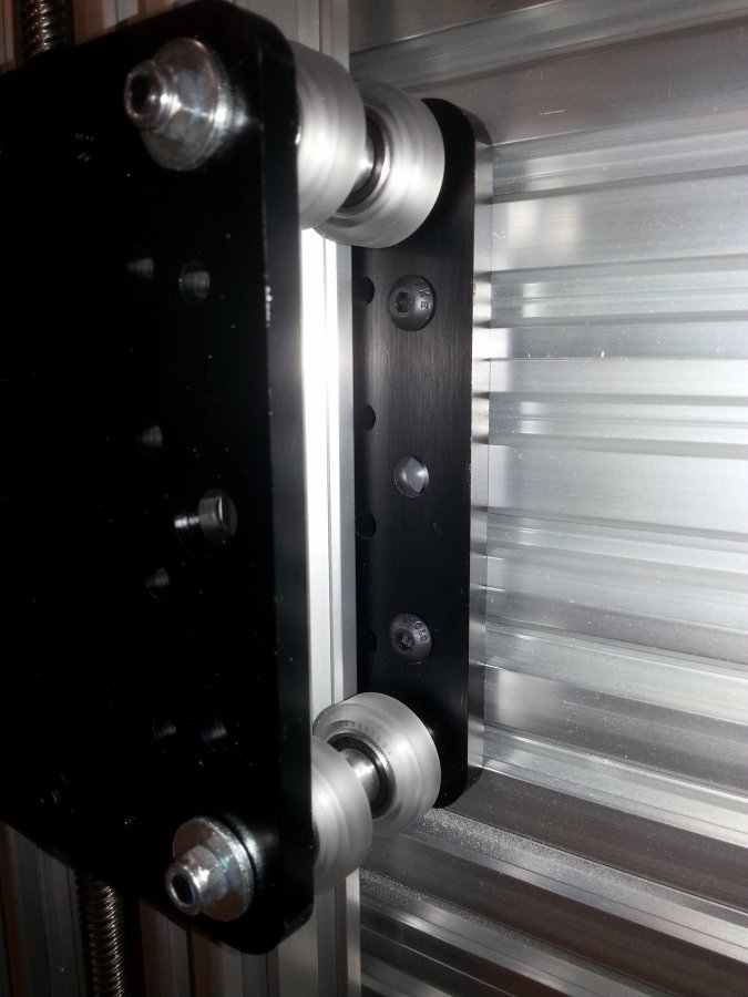
The only other mod I did to the build was to only use two spacer stacks between the X axis plates instead of the 4 on the original build. I put them in the center wheel holes instead of the outside holes near the wheels. This allows me to put 8 screws to hold the X and Z plates together instead of 4. Didn't really see the need for 4 spacer stacks. I think if I was building this machine for myself, I would have just put 12 wheels on the carriage instead of 8 anyway.
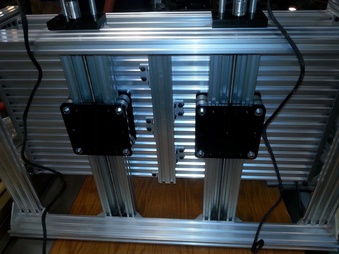
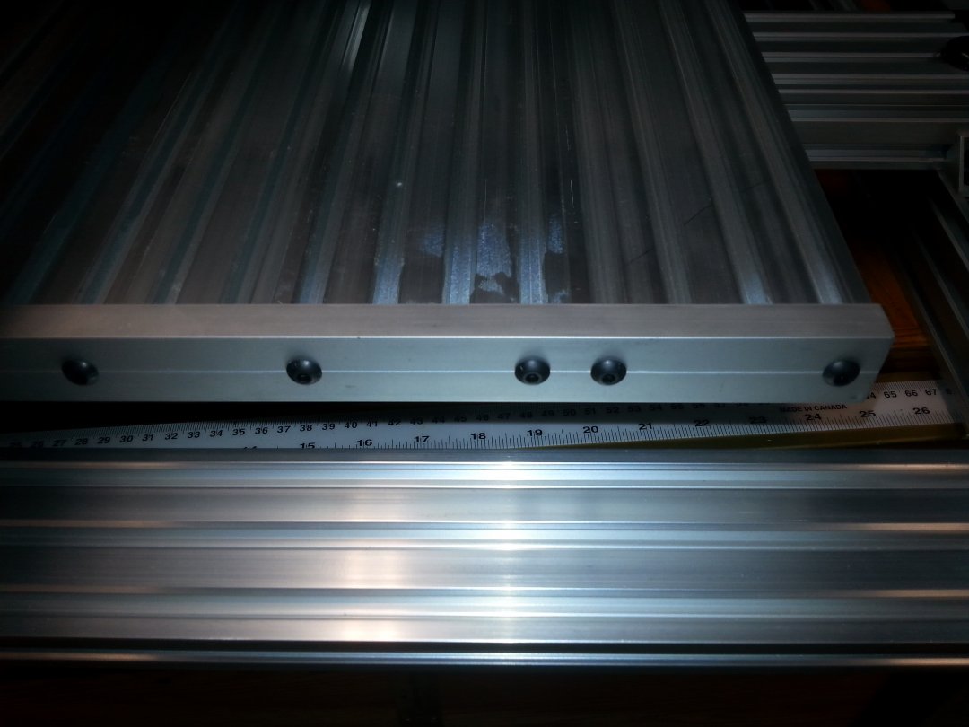
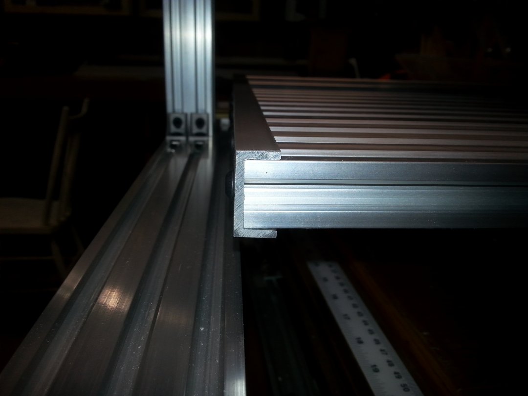
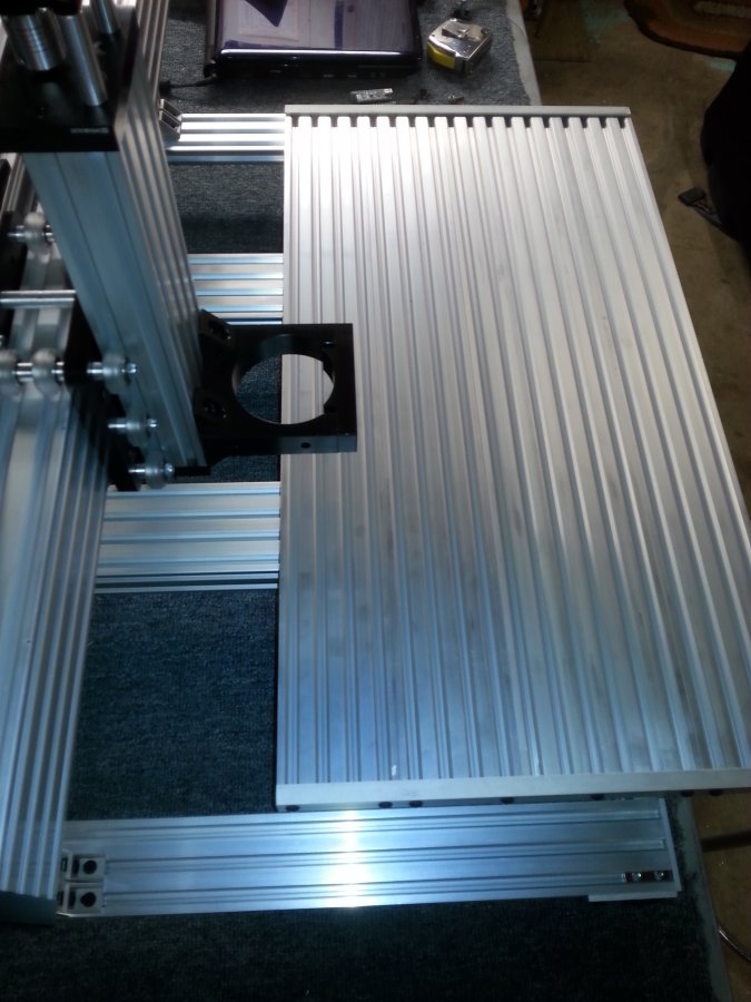
Now on to the table. I made the table 360mm wide, using (4) 20x80's and (1) 20x40. The 20x40 is sandwiched in the center with 2 20x80's on each side. This allows the mounting holes on the Y axis plates to land on the outside edges of two 20x80's for a bit more stable connection. You can see that I just used T-nuts and 12mm screws to connect the table to the Y gantry plates in 8 places, using unthreaded holes in the plates. This allowed me to screw the table on from the bottom with minimal fuss. The hex key goes through the hole on the other plate for a straight shot at the screw.
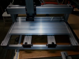
I built the table on the bench in one piece. I cut the 5 table pieces to 700mm length. This allowed plenty of clearance between the table and the uprights. I put a piece of 20x40 flat on the bottom of the table between the two Y axis actuators as a stiffener. It is attaches with 4 hole corner brackets, which straddle the joints between the v-slot. The corner brackets are staggered, so one joint is covered by a bracket on one side of the 20x40, and the next joint is covered by a bracket on the opposite side of the 20x40. These brackets help align the edges of the bed rails and keep the bed flat.
I made end covers for the bed rails using some aluminum miter slot track I had laying around. This is a thin wall u-channel used for putting miter tracks into homemade jig tables like router tables. It is 3/4" wide inside, which is a tad too small to fit over the end of the 20mm v-slot. So, I went to the router table, and widened the slot in the aluminum u channel with a straight cutting bit, taking a bit off each internal face and sneaking up on the fit. After I got it to fit good, I cut a couple of 360mm pieces off the track (it was 4' long) and drilled holes to mount it to the ends of the v-slot. I just put one screw at each side of each 20x80 for a total of 8 screws. One side of the bed I just used self tapping screws to attach the end channel, the other side I tapped with 5mm threads and used regular machine screws. This allows the tapped side to be removed to allow you to put t-nuts into the v-slot grooves for mounting stuff on the bed.
That's about it. I just have to build the electronics panel and wire it up and it's done. I like this so much, I am going to try a Big Ox style machine with the aluminum bed. I won't be able to use the u-channels, so I'll have to figure out some way to cover up the ends of the extrusion.
Keep Calm and Build Routers!!!
C-Beam XL with Aluminum Bed
Build in 'X/Y Table Style CNC Mill' published by Metalguru, Dec 3, 2016.
C-Beam XL with v-slot aluminum bed for fixturing.
-
-
Build Author Metalguru, Find all builds by Metalguru
-
- Loading...
-
Build Details
- Build License:
-
- CC - Attribution - CC BY

