
Introduction
This build will attempt a large 3D printer (nominal 2ft by 2ft by 2ft build volume) using primarily v-slot components for all three axis of motion (X,Y,Z). This configuration is that of a gantry robot.
About 4 years ago I purchased a Solidoodle 3 3D printer to hop on the 3D printer bandwagon or perhaps more appropriately join the stream of lemmings headed for the nearest cliff. My real interest was modeling (not the run way kind) a cartesian 3d printer's errors. Towards this end I wrote 2 Matlab programs recycled to some extent from my Applied Mathematics graduate project titled "Master's Project 2009 Error Analysis of Robot Arm Kinematics". The first was a Print-Test driver and the second one was a Monte Carlo simulation of the printer errors. The Print-Test driver provided the ability to run 30 tests of escalating build volume and error estimate assumptions. Test-30 was for a 609mm cube and the results are provided here. This was the genesis for the idea for a 2ft=609mm cube 3D printer.
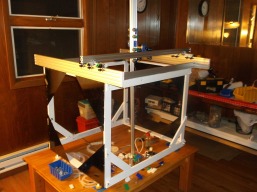
Officially my build started April 1,2017 but the frame shown was put together about 8 months prior. The frame is made from rail, that is , actual aluminum stair railing from my back yard that was replaced with recycled wrought iron from my sister's front porch remodeling. On top is fixed Makerslide rail primarily trying to use up the Makerslide rail before I start using my preferred V-slot rail.
Over the last several years I purchased V-slot rails and a smaller number of Makerslide rails and their respective required wheels and a few large plates. I 3D printed many Openbuild connectors and such in anticipation of starting the build. I purchased both Nema 17 and 23 stepper motors and a Ramps 1.4 kit and of course a large assortment of metric nuts and bolts required for the V-slot rails. Submitting a "build in progress" has given me the impetus to take the build seriously and devote a lot of time to it.
Build Activity
Stepper Motor Selection Requirements
The printing end (hot-end) of a 3D printer has an expected range of accelerations and velocities for each x-y-z direction. These velocities and accelerations are the driving requirements for any 3D printer, large or small. Along each of the axis, there is an effective inertia composed of both mass and rotational inertia. Each axis's inertial mass is due to the weight of structural components and the weight of any stepper motors. Each axis's rotational inertial is due to the stepper motor's rotor's rotational inertia. It is assumed that each axis is driven by one stepper's ability to generate torque. Torque is defined as the force acting tangentially at the stepper's output shaft or a lesser force acting at the stepper's pulley. This force must be able to accelerate and drive at required speed the axis's inertia loads including the stepper's rotational inertia. Detent torque and starting force (to overcome each axis's starting friction) will be integrated into the calculations. The power of each proposed stepper is to be computed and constrains which torque speed combinations are possible. Stepper motor specifications usually include a torque-speed graph which includes two curves defining the operating region for the stepper. The first "pull-in" curve identifies the set of all maximum torque-speed points for which the stepper will not lose synchronization during starts and stops. The second "pull-out" curve defines the set of maximum torque-speed points for which the stepper will not lose synchronization along as the stepper does accelerates or de-accelerates slowly. The region between these curves is called the "slew" region (TBS-figure).
This build has been more like a design in progress. Since v-slot components make it easy to assemble components into subassemblies such as the x-carriage it is just as easy to disassemble if a better design seems evident.
I recently assembled a carriage with a x-axis stepper and a z-axis stepper to control the 20 by 20 mm z-axis hot-end arm. I'm designing this on the go so it's no surprise that it's "better" i.e. more build volume will be available if I use 80 by 20 mm V-slot on the x-axis ends. This will elevate the x-axis rail so that the carriage assembly will clear the aluminum railing frame as depicted here. Before I go any further I'm going to step back and look at the mass of the different axis and what size Nema stepper motors are required. I have been assuming that the z-axis can be handled by a Nema-17. My trial x-z carriage uses a Nema-17 which must lift up and down without gearing the 20x20 hot-end arm which at present I am questioning. It should be noted that a Bowden extruder will be used to eliminate a stepper motor on the z-axis. My plan was to use a single Nema-23 stepper to drive the y-axis. I would set it up the way Solidoodle 3 did it. If you think about it the Solidoodle 3 is close to a Gantry design at least for the x and y axis. I need to establish my stepper motor torque requirements and do some testing prior to committing to a final design. I googled the specs for my Nema-17 and Nema-23.
Comparing the Nema-17 holding torque specs with information from Question: how much weight can my stepping motor lift? and Understanding Torque it became questionable if the Nema-17 was powerful enough to lift and hold the current z-axis of length 108 cm. A python program was written to determine the force available at the pulley for Nema-17 and Nema-23 steppers. Additionally, calculations were performed to determine the effective loads as seen by each z,x and y stepper motors. The results indicate z-axis Nema-17 can hold the 1.27 lb gravity load but must in addition be able to accelerate the z-axis inertial mass corresponding to it's weight of 1.27 lb but additionally must counter the external gravity force of 1.27 lb.. The weight of the x-axis is 3.64 lb and 5.59 lb for the y-axis but their steppers must move their inertia equivalents. Further analysis is required to determine if the steppers can meet the acceleration requirements. To assist in validating the viability of the planned Nema 17 and Nema 23 stepper selection usage in this design the following reference documentation was gathered:
- http://openbuilds.org/attachments/s...8/?temp_hash=a331dc35ee0939e81a649c07dc2f56a6 Step Motor Basics Guide
- /home/robert/Desktop/MY_BUILD/THE_BEST/super_stepper_selection_17112005105315.pdf
- TBS (To Be Supplied) ...
1,2,3 May 2017
The current status of the build is that the frame is now rigid with no sway. The makerslide/v-slot rails have been squared properly on top of the frame. The frame actually is out of square but that only affects reduces the x-y plane working area slightly. Measurements were performed to determine the starting force required to accelerate the frictional and inertia loads of the x,y and z axis assemblies from a dead stop. These forces were measured towards the ultimate goal of computing torque requirements. To these torques will be added the detent torque values from the stepper specs. Requirements that need to be defined include the following:
- motion profile (trapezoidal) requirements for each axis - get parameter ranges from Marlin firmware
- velocity: steps/mm X200 Y200 Z200
- acceleration: mm/s^2 X500 Y500 Z20
6 May 2017
- load inertia for each axis, F=ma, calculate masses from weight measurements- need stepper rotary inertia values.
- speed/torque curves for specific Nema-17,23
- acceleration torque, frictional torque
- determine maximum acceptable inertia ratio 5:1 typical (TBS-reference)
To date , torque-speed curves for the specific steppers have not been found. There are several options:
So far, the reference stepper selection tutorials and guides all require Torque-Speed curves. Of course they do. Somehow this data must be obtained or estimated.
- try to cross reference the steppers to ones for which data sheets can be obtained, so far no luck with this approach - "free data sheet site" didn't respond to a non-company
- take some torque-speed measurements - found some web content along this path
- model mathematically the steppers and run simulations to obtain the graphs - found an article describing this approach
- since power = torque * speed , if stepper power is constant can generate plots - doubtful this is correct
- ...... test steppers under real conditions, observe their performance
A selection of long metric screws were ordered today to allow for a rework of the x-axis carriage. A more symmetric, robust design is possible. The new x-carriage design will straddle the y-axis v-slot rail providing one side to accept the stepper x-axis drive and the other side will accommodate the z-axis stepper.
7 May - 4 June 2017
x-axis trolley
The x-axis trolley has been reworked as shown here and here. The new z-axis assembly as described below with be mounted to the x-axis trolley.
z-axis rework
The z-axis is being reworked using a 1000mm acme 8mm diameter threaded rod. It will work like a linear actuator with a minimum of 24 inches of travel. The part driven by the threaded rod will be a 20x20mm v-slot extrusion with the hotend attached. V-slot wheels will constrain the motion of the extrusion as depicted by the z-axis mockup. It was required to mill a special threaded rod block mount to interface with the 20x20mm extrusion. As part of the z-axis redesign, a 20x20mm drill guide was assembled with the goal of connecting 20x20mm extrusions directly without always using the the full or have blocks. V-slot wheels are used in pairs to constrain z-axis motion. One can be fixed and the other uses an eccentric nut for fine contact adjustment.
heat bed
A 24x24x0.25in carbon steel plate was purchased for the heat bed based on the fact that the coefficient of linear thermal expansion for aluminum is approximately twice that of steel's coefficient. This decision was made at the expense of increased heat bed power requirements. The specific heat capacity of aluminum is 0.220 Btu/(lb-degF) verus 0.120 Btu/(lb-degF) for carbon steel but the density of steel is 7850 kg/m3 versus 2720 kg/m3 for aluminum (6160). To heat two identical heat beds composed of steel (40 lbs) and alumimum (14 lbs) requires 4.8 Btu/(degF) verus 3.08 Btu/(degF). Aluminum power requirement is 64% of steel.
heat bed calculations/simulations
Current coarse calculations indicate that to heat the steel plate up to 100 degrees celius requires about 480 Btu. At 3412 Btu/hr per 1kw conversion identity it would take about 8.5 minutes to warm the plate. But this does not include the ongoing convection losses which I surmise are significant. A computer model is needed. The results may indicate a need to use an aluminum bed because of a wall socket's power limitations.
heat bed simulation
.......TBD.....
5 May - 28 June 2017
Completed assembly of new z-axis that uses an acme thread as the drive mechanism and v-slot wheels to guide the vertical movement. Future to-do list:
1 July 2017
- Mount y-axis stepper. -- 3 July 2017
- Mount end-stop switches.
- Design-install heat bed and associated electronics.
- Install all stepper motor drive belts. -- 2-3 July 2017
- Make laptop-arduino combo standalone stepper driver to test individual axis movements.-- 1 July 2017
- Mount Ramps electronics.
- Provide for a laptop stand integrated into the printer's frame.
- Mount power supplies.
- Engage flux capacitor.
- Mount switchable power strip for all AC power.
- Mount LED strip lighting.
- Assemble,mount and test Bowden extruder.
- Connect all steppers to RAMPS
- Connect all end-stop switches to RAMPS
- Connect sharpie pen to end of z-axis for initial x-y plane testing.
- Try a 3D print.
Referencing Arduino Control Stepper CD DVD Motor use A4988 driver with code
a laptop-arduino combo standalone stepper driver was fashioned to test individual axis movements. The blue top push button controls the rotational direction of the stepper. This shows the new stepper driver controlling a Nema-17 stepper and for the first time the z-axis is driven. A problem was encountered when the z-axis was driven towards the "top" position. It seemed to get "stuck" intermittently. This will be explored. Most likely, the rails are not perfectly parallel.
2 July 2017
The x-axis was driven today by the standalone stepper driver.
3 July 2017
The y-axis was driven today by the standalone stepper driver. A serious problem has been encountered. The commanded forward and backward movement are unreliable, getting stuck in one direction or another. A slight push will start the movement. Disconnecting only the Nema-23 drive belt, manually moving the y-axis assembly seems smooth enough but when the Nema-23 drive is reconnected and powered there seems to be significant drag encountered at different positions at different directions. The y-axis moves smoothly then falters when the reverse direction is commanded. So far, the y-axis rails where checked and were found to be parallel. Also, attempts at getting belt tensions right were tried with no clear improvements. Since it moves smoothly occasionally the working assumption is that this problem is solvable.
4 July 2017
Adjustable y-axis tensioners were fabricated from openbuild 3D parts with the hope that the y-axis drag problems could be solved. No such luck. Apparently, the y-axis rails are not quite parallel as evidenced by loosening some frame connectors. Also, since there are two trolleys that ride the two y-axis rails and each trolley has seven wheels each, the settings of the three eccentric spacers per trolley are questionable.
5 July 2017
By shedding parts of the y-axis assembly, it was discovered that the y-axis drive problem persisted even when the entire x-axis rail including the z-axis assembly was removed. Then the belt on the right y-axis was disconnected and then the left and finally the y-axis stepper belt was disconnected. The problem persisted. The "arduino standalone stepper driver" is flakey! It does not react reliably to the blue button which is supposed to change it's direction. I did not bother to check the A4988 Vref voltage and adjust it. This value when measured indicated over 1 volt which translates into 2 amperes current. The A4988 was set at too high a current value and is designed to shutdown to avoid overheating. This would explain the stepper starting and stopping or failing to start. The Vref was turned down to about 650 mV corresponding to a more reasonable 1.3 A. Well, the arduino program was changed with respect to the pulse durations and the time between pulses with the result that the left and right y-axis trolleys are being driven reliably now. The next step will be to adjust the y-axis trolleys for optimum contact before reinstalling the x-axis and z-axis composite assembly.
6-15 July 2017
The y-axis trolleys were simplified by using only 4 wheels vice 7 wheels. The extra wheels made adjustment of the eccentric spacers more difficult. Adjusting even four wheels can be tedious as the wheel assembly itself has both angular and vertical movement before tightening. If not real careful one could tighten the wheels either high or low vertically to the rail groove. Also, the wheels could be tightened with the wheels slightly skewed causing the wheels to drag in the groove. These considerations combined with eccentric wheel adjustments resulted in the y-axis having movement problems after the x-axis/z-axis assembly was re-installed. Movement is unreliably smooth. The y-axis moves with a shuddering noise which seems to be coming from the Nema-23. The belt tension was adjusted and the perpendicularity of the y-axis rails with respect to the x-axis was checked. It may be the stepper driver current setting is too low. This statement is made because when the y-axis movement is slow and making noise if it's given the slightest "push" it will start moving faster and smoothly and the stepper noise changes to a higher pitch. There is one other variable to consider. The y-axis belts are threaded inside the y-axis rails and are threaded through the y-axis trolleys with the potential for the y-axis trolley extrusions to "catch" the belt teeth. Although this has been hard to verify, it may account for the "stuttering" noise heard. In conclusion, the y-axis trolleys have too much friction and a re-design is warranted. The new design needs to have wheels that roll on top of the y-axis rails and should not have belt friction problems.
16-19 July 2017
The y-axis belt idler pulleys and termination locations have been redesigned to keep the belts horizontal and out of contact with anything else. This necessitated a y-axis stepper motor mount upgrade.
For the heat bed, a 2 ft by 2ft by 1/4 inch aluminum plate, a digital heat controller and 10 100watt 50 ohm power resistors were purchased or ordered. Methods to "average" multiple NTC thermistors were researched.
One thing is certain is that the Nema-23 stepper motor or the arduino based driver is not working correctly. This was easily ascertained by disconnecting its' drive belt and observing its' erratic performance with no load. It is time to examine it with an oscilloscope.
Meanwhile, re-installing a 2004 student version of MATLAB with the PDE toolbox is underway. This is necessary to do the heat bed simulation.
Another problem encountered is the breaking of 3D printed parts integral to the x-axis carriage. The Openbuilds aluminum versions have been used in certain places and have been used exclusively on the re-worked y-axis trolleys. The x-axis carriage will be redesigned with aluminum components mostly.
If it turns out that the Nema-23 can drive the gantry assembly reliably then it will be retested with an extruder temporarily attached to the z-axis hot-end. The goal is to abandon the Bowden extruder plan as it is viewed as possibly and probably problematic.
20-24 July 2017
Got my 2004 student version of Matlab working. It wouldn't re-install to Ubuntu 17 so I had to download an Ubuntu 11.10 iso image and install it to Virtualbox. Only then could Matlab and the PDE toolbox be re-installed. Mathworks online documentation for its' latest version provides an example for a heated horizontal plate including convection. The old version I have does not support the functions used in the current simulation. I will use the version I have to model the horizontal plate with 10 heat sources i.e. power resistors and estimate the free convection losses external to the simulation.
The arduino standalone stepper driver setup which proved to be unreliable due to apparent loose connections was revisited and some breadboard components and connections were now soldered. This has resulted in smooth y-axis stepper performance (fingers crossed). A Nema-17 stepper motor was attached temporarily to the end of the z-axis and the y-axis stepper didn't seem to notice the additional weight. This is good news as using a Bowden extruder can be avoided.
25-27 July 2017
The x-axis trolley was reworked replacing the broken 3D printed angle connectors with Openbuild aluminum versions. Also, separate plates have been bolted to the x-axis trolley and z-axis assembly. This facilitates the assembly as the x-axis can attached to the x-axis rail and then the z-axis assembly is easily bolted to the x-axis trolley. It has become apparent that the x-axis rail and x-axis trolley is not rigid enough. Putting a little torque on the z-axis causes the entire z-axis assembly to rotate a little around the x-axis trolley. The z-axis becomes a large moment arm which torques the 20mm x 40mm extrusion. The x-axis trolley consists of two wheels on top of the x-axis extrusion and two wheels underneath the extrusion. This allows some rotation about the x-axis which would translate into large errors at the extruder. Also, upon further inspection at least some of the rotational play is visible at the angle connectors that join the x-axis rail to the y-axis trolleys. Looks like another redesign of the x-axis rail, x-trolley, and y-axis trolleys is warranted.
Meanwhile, the lastest home edition of Matlab with PDE toolbox has been ordered and should make simulating the heat plate with free convection easy.
28 July -10 August 2017
The 2017 version of Matlab with PDE toolbox has been purchased and received. Working through some of the PDE examples. Their demo thermal problem for a metal slab i.e. small thickness compared to other dimensions is treated as a 2D problem without specifying a thickness and the demo uses a function with an argument "MassDensity" which is a 3D quantity. Probably one is supposed to convert the MassDensity to a corresponding surface density which is the only logical choice. This assumption is being verified by modifying their 2D demo program for a geometry whose results can be easily verified on paper.
The 20mm by 40mm x-axis gantry rail has been replaced with 20mm by 80mm v-slot rail. This required fabricating (manually) end plates for the y-axis trolleys and required new plates for the x-axis trolley with a new Nema-23 stepper motor. Also, the y-axis stepper motor now has a new motor mount that can easily adjust the belt tension. The y-axis belts were raised for the higher x-axis rail and the old belt tensioners need to be reworked based on the new configuration.
The x-axis with attached z-axis assembly was driven by the standalone arduino driver. The x-axis moved smoothly except for a certain location. The belt is damaged in the vicinity of the motion problem and the problem is being worked.
11 Aug - 5 Feb 2018
I have been derailed during this period due to medical issues and moving 100 miles away from my former home. My 3D printer is yet unpacked but I did purchase a variety of C-beams which should make for a better z-axis.
5 Feb 2018 - 25 March 2018
I have returned to the MATLAB thin heat plate simulation. Well progress on the heat plate simulation has been disappointedly slow and difficult. I have no experience with the Matlab R2018a (latest) Partial Differential Equation (PDE) toolbox. I have at least 6 years in industry programming Matlab for other types of simulations. My problem has been trying to get consistent results between several ways Matlab allows you to use the PDE toolbox. Mostly the problem is understanding how they define heat flux with respect to "edges" or why "faces" don't work. I have modified their thin plate heat problem with includes both convection and radiation to include a "heat in" lump sum value of 900 watts. This simulation seems to work okay. However, I am not able to get consistent results when I attempt to model the same thin plate with 9 square holes in the plate to which I apply boundary conditions to the inside edges of the squares expecting to generate a plate max temperature. The simulation is here. If anyone actually reads this and can help it is appreciated. I put in a question to Matlab questions & answers yesterday. Maybe I'll get an answer.
26 March -7 April 2018
Ran a heat plate simulation using a 900 W internal heat source that produces this temperature profile. Also ran a heat plate simulation using a 900 W heat flux along the plate perimeter that produces this temperature profile. The simulation results as evidenced by their different temperature profiles don't match up. Heat flux into the plate perimeter results in faster temperature rise times and about 100 degrees hotter than the internal heat input simulation. In either case their is qualitative evidence that convection and radiation limit the maximum temperature of the plate as expected. I don't know which simulation to believe and I've had enough of wasting any more time on this. Nine 100W resistors will probably do fine.
8 April 2018
Time to unpack my 3D printer and start putting it back together and look at how I can swap C-beam components into my Z-axis kludge.
Large cartesian gantry style 3D printer
Build in '3D PRINTER BUILDS' published by Robert E. Nee, Apr 8, 2018.
This will be a fixed bed, v-slot implemented X,Y,Z axis gantry style 3D printer.
-
-
Build Author Robert E. Nee, Find all builds by Robert E. Nee
-
- Loading...
-
Build Details
- Build License:
-
- CC - Attribution - CC BY
Reason for this Build
This build is to attempt a build without rods, acme screws. I will use just v-slot (and some makerslide) rails and components.


