
This a WIP:
Currently I have a DIY lasercutter made from 25x25mm Alu tubing - as an upgrade I ordered some v-slot that should arrive next week, this will then begin the build of my V2 laser
This build will be continually updated: As is, the BOM is proven so you can start ordering if you'd like to...
Submission log:
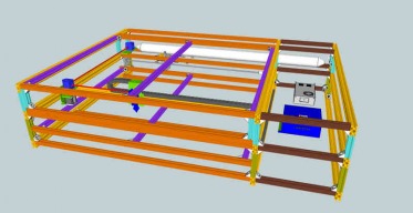
Image Gallery:
- 9 August 2014: Created project
- 10 Aug: 2AM - uploaded version of Sketchup file with the frame added, as well as motors and 24v PSU
- 10 Aug 10AM - uploaded version of Sketchup file with the corner brackets, laser PSU, Brackets for the stepper motors, mounting brackets for the laser tube. mounts for the Driveshaft (8mm shaft running through F608Z Bearings)
- 10 Aug 10:15: Uploaded a PDF invoice of what I paid for the SDZ laser parts - in reply to request from discussion page.
- 10 Aug 12:30: Added renders to Build Instructions (Draft) - pending delivery of VSlot to verify and take better pictures of each step
- 12 Aug: Added Driveshaft, Y carriage belt mounting and tensioner, Lid and optimised placement of X rail to prevent damage to laser head and maximise cutting area
- 16 Aug: Added uprights to mount firewall between cutting area and rest of machine (to allow for vacuum chamber to exhaust smoke). Validated corner brackets match mye existing sketches to ensure count is correct
- 16 Aug: Updated BOM to most current state, should now be 99% complete - at least in regards to parts to order from OpenBuilds.com, Lightobject.com and SDZLaser.com. May need some extras sourced locally
- 23 Aug: FairShare Programme sent me the V Slot as required to complete the build and thus update the Build Instructions with clear video/photo/etc. Also ordered Door Handles, Slot Covers (to neatly wire this machine) Idler Pulleys, Belt Tension Springs and Belt Clamps
- 25 Aug: Ordered the lasercut metal parts. Uploaded the DXF files as ordered
- 25 Aug: Added the Cable chains to the Sketchup Model - to render the assembly instructions from
- 14 Sept: Cut all the V-Slot to lenghts: https://plus.google.com/104034368033227202956/posts/XUwXwm8ztph
- 24 Sept: Version 3 Laser controller - arrived and assembled: tested OK. See https://plus.google.com/104034368033227202956/posts/HrTzrHxQMn2
- 15 Sept: Test fit of X carriage parts: https://plus.google.com/104034368033227202956/posts/Qi26Yn4FYeA - I wasnt yet happy - could look better (functionally OK but I'd redo it as a V2 where the belt is at the back. Did just that...
- 30 Sept: Did get the V2 X Axis parts back from manufacturing and test fit perfect: see https://plus.google.com/104034368033227202956/posts/c1nY7z157LF and https://plus.google.com/104034368033227202956/posts/TAbfz4j714j Now I'm happy
- 6 Oct 2014: Selling off the V1 laser to clear up space in the workshop to start the actual build. Also built myself two new tables to do the construction on https://plus.google.com/104034368033227202956/posts/QpwqGQX3aaK
- Dec 2014: Sold off most of the Hardware to Theo Moelich to do the actual Beta build and help me take pictures of the steps. With all the pressure at work I haven't found time to do the build in the past few months! Very sad to have it go, but at least it benefits you the reader as there is actual build progress!
- Set up an Imgur account to post all the build pics since uploading it here is not quite so easy yet
OpenBuild FreeBurn CO2 Laser Cutter Build
OpenBuild FreeBurn CO2 Laser Cutter Build
Build Instructions:
Note: The full sketchup model should ALWAYS be consulted while building to determine final positions
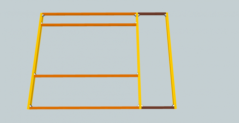
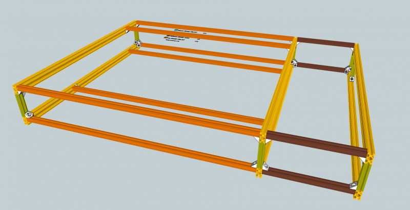
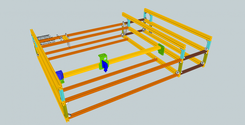
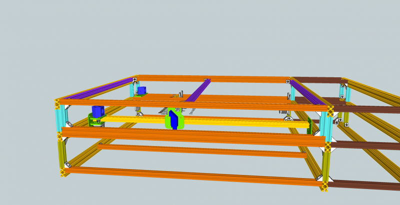
1. Assemble the Frame
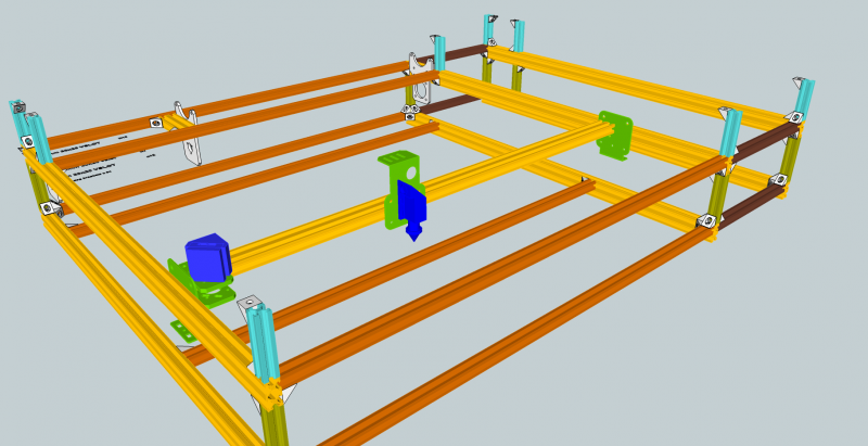
1.1: Assemble Base
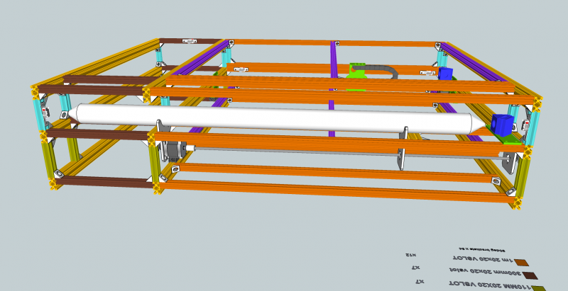
Place 3 x 1000mm 20x40s vertically, and install the 4 x 1000mm 20x20s in position between the left two. On the rights, install 2 x 300mm 20x20s.
1.2: Install 110mm 20x20 uprights as shown
(note where we say install: Use Corner brackets and M5 screws with T Nuts, consult sketchup model for orientation)
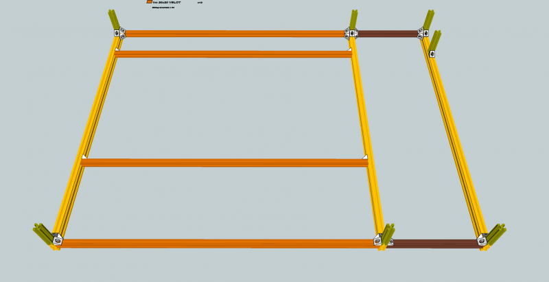
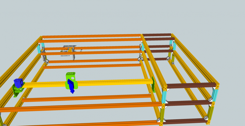
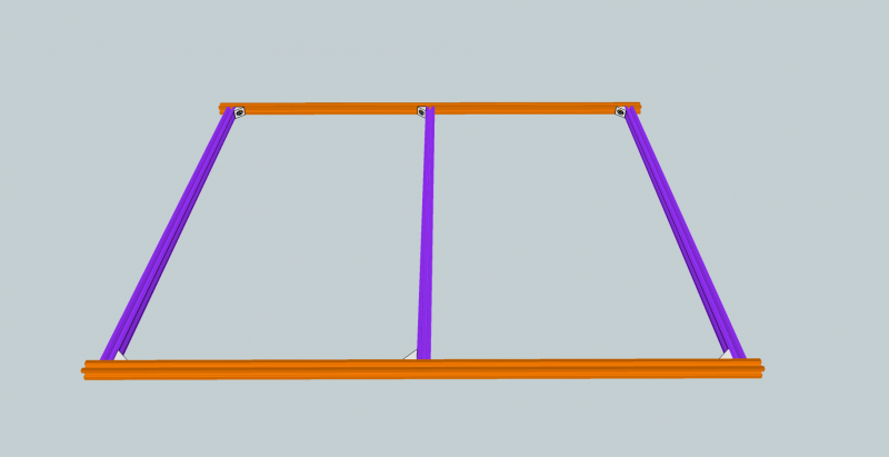
1.3 Install the middle tier vertical rails: 3 x 1000mm 20x40s
Another view of the middle tier vertical rails:
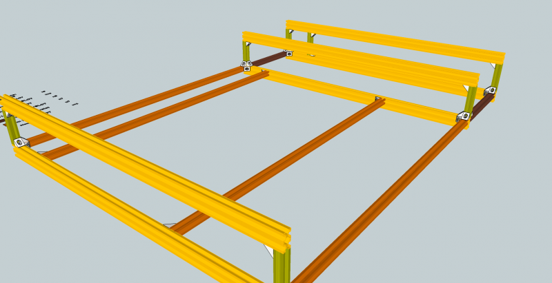
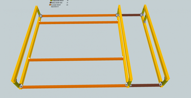
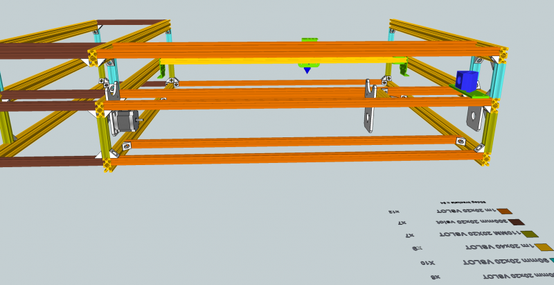
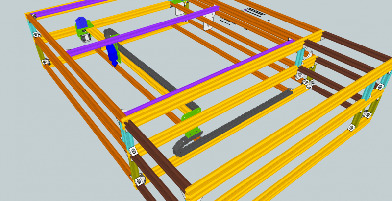
1.4: Install horizontals for the middle tier:
3 x 1000mm 20x20s and 2 x 300mm 20x20s:
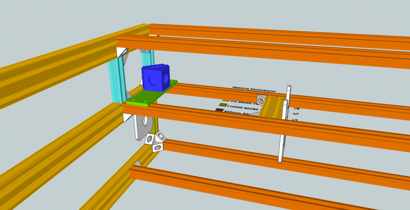
1.5: Install the 6mm Aluminum Tube and Driveshaft holder pieces.
The middle holder is first installed on a small piece of 20x40 between the two horizontals (see Sketchup model)
1.6: Subassembly: Build the X Axis
(I will update this section with step by step photos shortly)
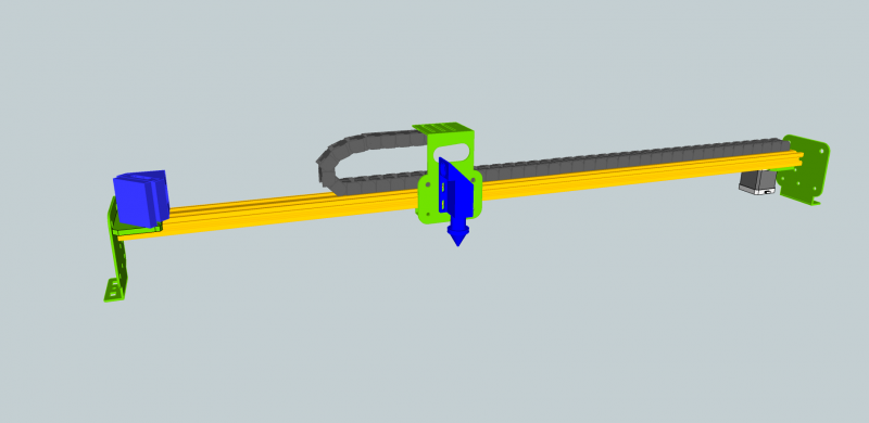
Install the No.2 Mirror mount on the Idler plate, and mount that one one end of a 1000mm 20x40. Note you may need to trim the end of this beam to fit between the two carriages on the rails to allow for the spacing of the carriages and their thickness: approx 10mm or less to be removed
Install the X Carriage (can't slide it on later once both carriage plates are bolted to the ends)
At this point its easier to first install the Laser head on the carriage than trying to install it later. YMMV depending your laser head (if you don't get the recommended one)
On the other end install the Motor mounting plate on the under side (clearance for the cable chain along the top therefore installing on the bottom. Install the pulley as well, and the other side's Y carriage
1.7: Install the entire X Axis onto the rails you built in step 1.4
Note that you may need to remove the one side's Y carriage and shave off a few mm of the bar to allow it to fit perfectly between the two Y carriages without pushing the wheels to the side.

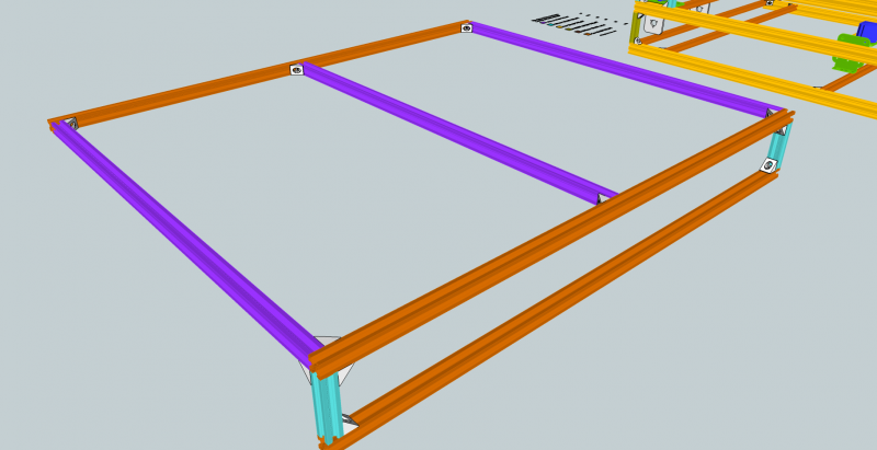
1.8: Install the 90mm 20x20 uprights
For the second tier
1.9: Install 3 x 1000mm 20x40s on top of the 90mm uprights
Consult the Sketchup model for orientation and positioning of the rails and corner brackets
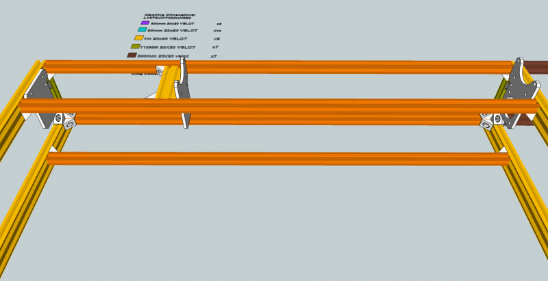
1.10: Install Firewall Support beam
Install a 300mm 20x20 as shown in the right side compartment, between the middle level verticals

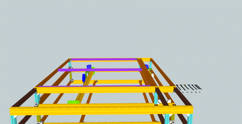
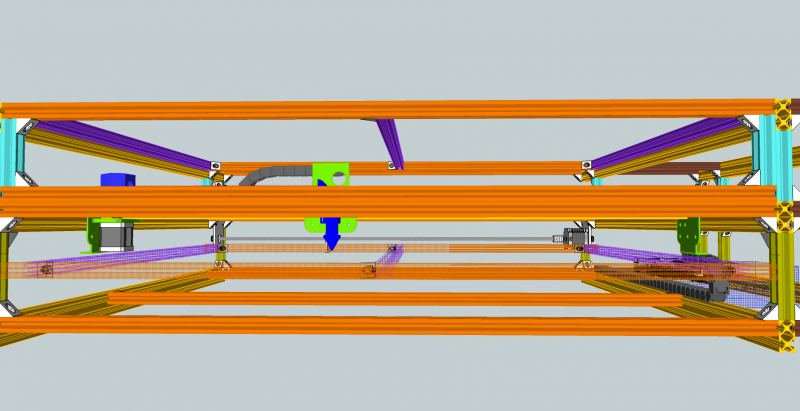
1.11: Install Top horizontals
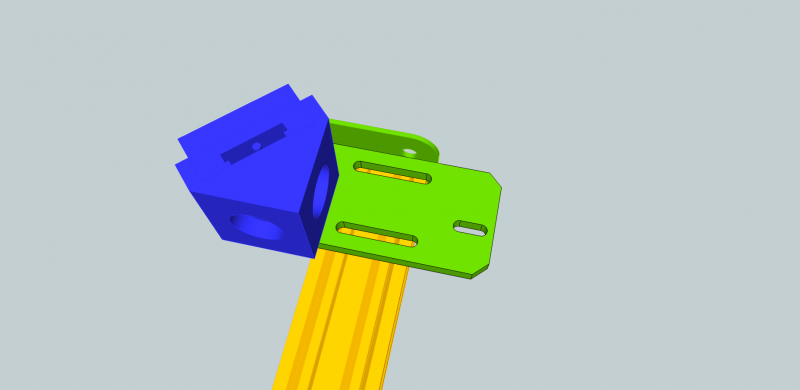
1.12: Install the No.1 Mirror mount bracket and Mirror mount
Install the 6mm Aluminum bracket over the two horisontals on the middle level using M5 screws and drop-in nuts, and then install the No.1 mirror mount into the bracket with M6 bolts from below
1.13: Subassembly: Build the lid
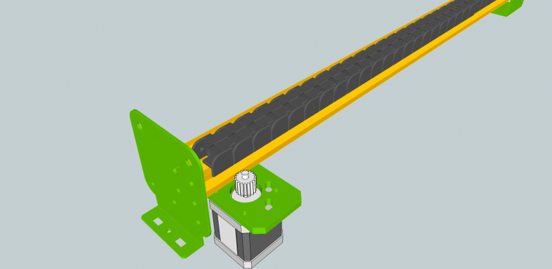
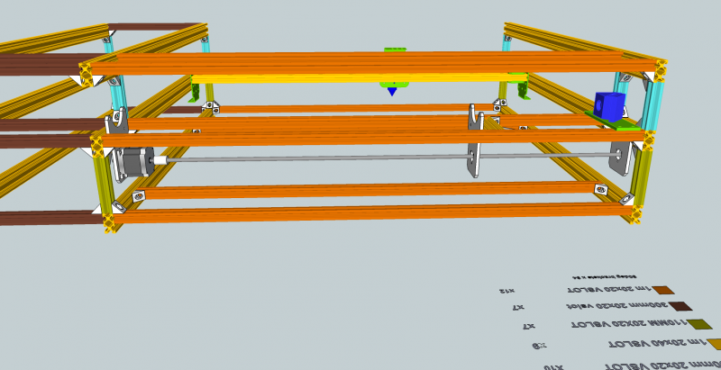
1.14: Install the rear NEMA23 Dual Shaft motor
1.15: Install the shaft coupler and Y Axis driveshaft:
Place 2 x F608Z Flange Bearings in the drive shaft holders and tighten them down with M3 screws and washers. Slide the drive shaft through and into the shaft coupler that you mount onto the rear facing shaft of the dual shaft NEMA23
1.16: Install the NEMA17 on the X Axis (Photo's to follow)
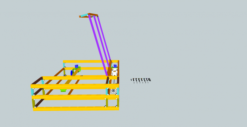
1.17: Install the Lid using a few Aluminum Hinges on the top horisontals.
At this step you can also add the gas lift struts, etc
Lid in Open position:
Lid in Closed position
Lid from front
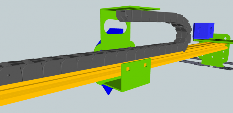
1.18: Install the Cable Chains on the X Axis and on the right of the Y Axis
Not shown here but the cable chains are routed to lie in cable chain trays cut from 1.5mm Aluminum. Will update with photos later - it will be more clear then
1.19: Install static Bed
Optional Powered Z Axis is coming soon but for testing purposes (or low budget version) you can install a fix height cutting bed. The laser head allows focusing distance to be adjusted to ensure proper focus even if bed cannot adjust in height.
Example Bed:
1.20: Install the laser tube
Lay down tube in brackets (line with foam tape first) and secure with rubber bungie cords (not too tight)
2. Install Belts: Photos to follow
I did not render the belts in sketchup but their placing is quite logical. The steps are basically:
2.1 Install the Y axis idlers: 2 x metal brackets with 2 x OpenBuilds Idlers
2.2 Install the belts using the folderover+cabletie method.
openBuilds FreeBURN-1 V-slot CO2 Laser (60-100w)
Build in 'Laser Cutter Builds' published by openhardwarecoza, Sep 13, 2017.
DIY Lasercutter: Budget orientated, medium sized (60-100w), safety first, based on Lasersaur software toolchain
-
-
Build Author openhardwarecoza, Find all builds by openhardwarecoza
-
- Loading...
-
Build Details
- Build License:
-
- CC - Attribution Share Alike - CC BY SA
Reason for this Build
Needed an Open Source Lasercutter that
a) is affordable and
b) superior to the current choices on the market -
Attached Files:
Parts list
Qty Part Name Part Link Comments 1 Parts List attached Link -
Attached Files:


