Current Status: 2018-04-14 Operational, have been printing in production for a couple months now.
To-Dos:
- Print out a benchy for you guys to verify build quality.
- Going through my parts line by line to double check the counts/URL links. Only did a single pass during each assembly.
- Expand the printer, currently not utilizing all of the default print bed.
- Possibly add an extrusion (currently using the AirTripper).
- Maybe redoing a custom Print Bed assembly to avoid RepRap Y-frog lasercutting.
X Axis:
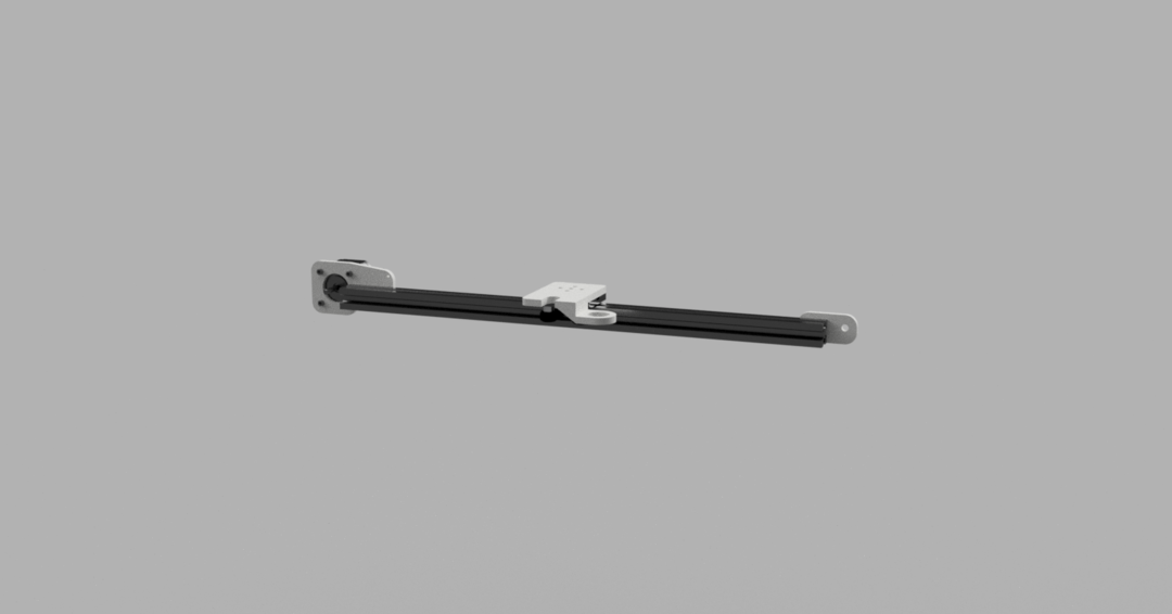
Last updated: 2017-09-17
Summary: Pretty simple design, this uses the mini gantry from openbuilds and belt drives for the X-axis. The Y axis contains the mounting brackets to attach this so we'll get to that later.
Bill of Materials:
Instructions:
- 1 Mini V Gantry Set
- 1 X-Axis Motor Mount (STL)
- 1 X-Axis Wheel Mount (STL)
- 1 Hotend Mount (STL)
- 1 450mm 20x20 Aluminum Extrusion (Black anodized for cool points)
- 1 NEMA 17 Motor (reference model is using this)
- 1 Smooth Idler Pulley Wheel Kit
- 1 GT2-2M Timing Pulley 30 Tooth
- 4ft of GT2 Timing Belt
- 4 M3 10mm screws (for fastening motor, may vary depending on motor type)
- 4 M5 10mm screws
- 4 M5 T-Slot Nuts
Y Axis:
- Assemble the mini v gantry following the openbuilds spec and slide it first into the center of the extrusion.
- Use 2 square T-nuts on either end for the motor and wheel brackets.
- Attach both ends so that the wheel and gear are about 5mm from the extrusion, we'll tighten it later.
- Run the belt so that the underside is inside of the extrusion slot, and the top is running above the top of the extrusion, the wheel and gear should naturally put it in this position.
- Wrap the belt through the slots of the mini gantry, then use some zip ties to fasten them down. I prefer to use two zip ties on each end so it doesn't slip. This should be snug but don't worry about tightness.
- After the belt is looped through the gear, wheel, and is attached to the gantry, loosen the wheel end bracket and push it out to tighten the belt, then re-tighten the bracket.
- Use the 4 low profile 10mm screws to fasten the hot end mount to the top of the gantry plate.

Last updated: 2017-11-04
Summary: After you finish the y-axis the x and y together will look like the above. This axis similarly uses mini v gantry plates sets for each side, and will be driven by two motors. I originally wanted to set this up to drive from a single motor to eventually convert to a cantilever design, but found more precise arcs after adding the second.
Bill of Materials:
- 2 Mini V Gantry Set
- 2 450mm 20x20 Aluminum Extrusion (Black anodized for cool points)
- 2 GT2-2M Timing Pulley 30 Tooth
- 8ft of GT2 Timing Belt (2 segments of 4ft)
- 2 Y Axis Wheel Plates (STL)
- 2 Y Axis Motor Plates (STL)
- 4 Y Axis Belt Guides (STL)
- 1 Y Axis Carriage (STL)
- 1 Y Axis w Endstop Carriage (STL)
- 2 NEMA 17 Motor (reference model is using this)
- 2 M5 x 25mm bolts
- 2 Mini Ball Bearing 105zz 5x10x4
- 4 M5 washers
- 2 M5 nuts
- 8 M3 10mm screws (for fastening motor, may vary depending on motor type)
- 16 M5 10mm screws
- 16 M5 T-Slot Nuts
Instructions:
Printer Body:
- Assemble the mini v gantry following the openbuilds spec and slide them both into the center of the extrusions.
- Use 2 square T-nuts on either end for the motor and wheel brackets.
- Assemble the wheel kit and insert it into the wheel bracket. I found success in order with bolt, plastic bracket, 2 washers, belt guide, mini ball bearing, belt guide, nut. The goal here is to have the bearing center over the extrusion, and the belt should run alongside the top of the extrusion and through the top slot of the extrusion.
- Attach the NEMA motor with the timing pulley to each side, then run the belt and attach it to the gantry plate. I use two zip ties each side, I've even gotten by with a binder clip in a pinch (pun unintended).
- Fasten the carriages to the gantry plates with the low profile screws included, the model should be counter-sunk so that the screws will not protrude from the top and hit the X axis. Depending on whether your endstop is X-min or X-max, place the endstop carriage with the hot end attachment on the corresponding side.
- Slide 2 T-Slot nuts into each end of the assembled X-Axis, then mount them to the carriages with 2 M5 10mm screws on each side.
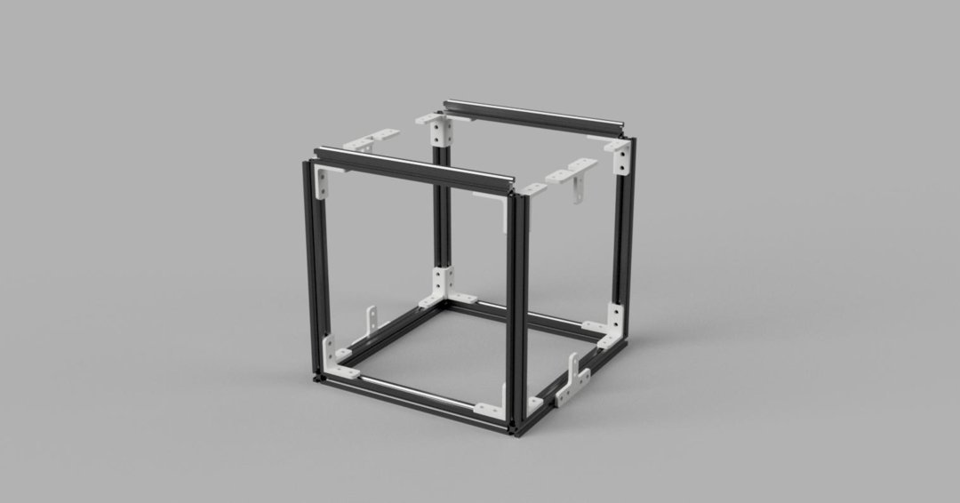
Last updated: 2018-04-14
Summary: This is straight forward, tried to keep this one simple and not mess with enclosures or doors. Tweak the extrusion lengths depending on how big of a print bed you want, right now with these lengths I'm at about 200mm x 190mm x 150mm.
Bill of Materials:
Instructions:
- 4 290mm 20x20 Aluminum Extrusion
- 4 300mm 20x20 Aluminum Extrusion
- 2 340mm 20x20 Aluminum Extrusion
- 8 Printer Body Joints (STL)
- 2 Z Axis Bottom Joints (STL)
- 2 Z Axis Upper Joints (STL)
- 88 M5 10mm screws
- 88 M5 T-Slot Nuts
- 88 M5 washers
- Starting with the bottom face, the two 340mm lengths will go along the Y-Axis. The 290mm extrusions will go along the X-Axis. Lay down the 4 extrusions and mount the Z Axis Bottom Joints and 4 Printer Body Joints.
- Add the 4 300mm extrusions for the Z-Axis, the last 2 will be the extrusions that are part of the Z-Axis Assembly.
- The Y-Axis Assembly will make up the last two extrusions to attach to the printer body joints.
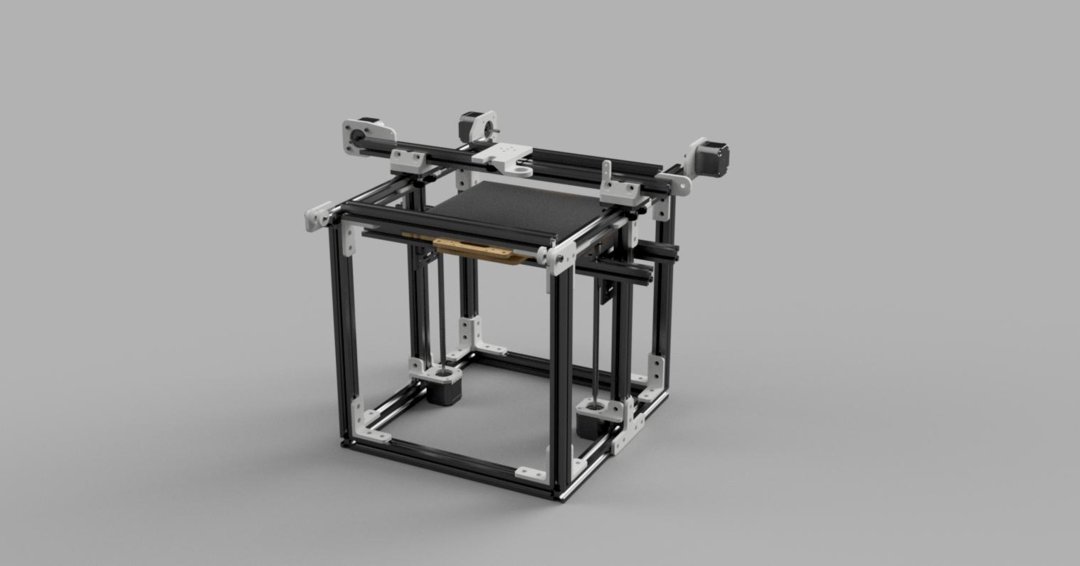
Z Axis:

Last updated: 2018-04-14
Summary: This will be assembled after the printer body frame, then the X-Y gantry will go on top. This axis will use the 20mm v-slot gantry plates sets for each side rather than the minis, and will be driven by two motors. The laser cut wood parts should be the RepRap kit for consistency sake. I don't have a Z-Axis Endstop for this because I opted to use a sheet of glass with copper tape on it and a bed leveling probe. I personally prefer it a lot, but it probably wouldn't be hard to rig something to trigger the endstop.
Bill of Materials:
Instructions:
- 2 20mm V-Slot Gantry Sets
- 2 420mm 20x20 Aluminum Extrusion (Black anodized for cool points)
- 2 300mm 20x20 Aluminum Extrusion (Black anodized for cool points)
- 2 Z Axis Motor Mounts (STL)
- 2 Z Axis Rod Mounts (STL)
- 1 Z Axis Print Bed Mount (STL)
- 2 NEMA 17 Motor (reference model is using this)
- 2 5mm * 8mm Couplers
- 2 8mm Metric Acme Threaded Rods
- 2 Nut Plates for 8mm Threaded Rods
- 1 RepRap Y-Axis Y-Frog Assembly
- 4 M5 x 25mm bolts
- 16 M5 10mm screws
- 16 M5 T-Slot Nuts
- 16 M5 washers
- 16 M5 nuts
- 8 M3 10mm screws (for fastening motor, may vary depending on motor type)
- Assemble the v gantry sets following the openbuilds spec and slide them both into the center of the 300mm extrusions.
- Attach the two motor mounts to the extrusion with M5 screws.
- Attach the NEMA motors to the motor mounts, then add the coupler, threaded rod, and nut plate.
- Screw the rod mount into the center slots of the v gantry plates using the M5 x 25mm bolts. You'll want to use 2 washers in between the rod mount and the v-slot plate, to compensate for the low profile screw heads that will be protruding from the plate.
- Slide the two 420mm extrusions through the rod mounts and connect them. Make sure to include 2 t-slot nuts in the center of each extrusion for the print bed mount.
- [Procure RepRap Y-Frog somehow, kinda up to you there if you want to buy it/make it/find a friend/etc]
- You'll mount the RepRap Y-Frog with the Print Bed Mount STL.
Mount the X/Y Gantry onto the Printer Body with Z-Axis and you're set:
Background:
Began in July 2017, CAD done using Autodesk Fusion 360. Going to upload the STLs here and the list of build materials. Tried to source everything I can through openbuilds for consistency, a few self printed parts and remnants from the Mendelmax used where applicable.
This build began back from the Mendelmax 1.5 printer I had been using for a couple years now. Moving the entire print bed for the Y-axis was so much mass that it caused vibrations in my prints, which spurred me to trying to CAD my own cartesian printer.
Additionally, I had already started slowly replacing the smooth rods commonly used on the Mendel design for the X/Y Axes into Openbuilds extrusion, and found quicker/lighter movement, and a lower noise volume compared to the linear bearings rattling (I live in a studio).
Not doing any fancy core-xy here (maybe convert this in the future to it, not sure), but have found this to so far resolve my problems.
The extrusion cuts may not be ideal for most, was trying to reuse all of the extrusions I had from the Mendelmax and a few leftover from another side project, so feel free to tweak those numbers.

Skyggen 3D Printer
Build in 'Cartesian Style Bots' published by Polymergraphy, Apr 15, 2018.
GT2 belt-driven Cartesian 3D Printer on an OpenBuilds Extrusion gantry, developed through Autodesk Fusion 360.
-
-
Build Author Polymergraphy, Find all builds by Polymergraphy
-
- Loading...
-
Build Details
- Build License:
-
- CC - Attribution NonCommercial - CC BY NC
Reason for this Build
I kept trying to cut weight on the bed for the Mendelmax design so I could run it faster, and eventually gave up for this gantry-style which I find to be a much lighter operation. I feel the stationary bed improves layer adhesion.Inspired by
Ubermeisters inspired me a lot to build this, he mentored me for a long time and I always wanted to rise to his level. -
Parts list
Qty Part Name Part Link Comments 2 20x20 V-Slot Linear Rail, 420mm (Y Axis) http://openbuildspartstore.com/v-slot-linear-rail/ Link Cut to 420mm, and pay for the anodized black because it's that cool. 1 20x20 V-Slot Linear Rail, 450mm (X Axis) http://openbuildspartstore.com/v-slot-linear-rail/ Link Cut to 450mm, and pay for the anodized black because it's that cool. 4 20x20 V-Slot Linear Rail, 290mm (Chassis) http://openbuildspartstore.com/v-slot-linear-rail/ Link Cut to 290mm, I know that's a weird dimension, leftover extrusion I had at the time. 6 20x20 V-Slot Linear Rail, 300mm (Chassis/ Z Axis) http://openbuildspartstore.com/v-slot-linear-rail/ Link Cut to 300mm 2 20x20 V-Slot Linear Rail, 340mm (Chassis) http://openbuildspartstore.com/v-slot-linear-rail/ Link Cut to 340mm 3 Mini V Gantry from Openbuilds http://openbuildspartstore.com/mini-v-gantry-set/ Link 1 is used for X-Axis, 2 are used for Y-Axis 2 20mm V-Slot Gantry Set from Openbuilds http://openbuildspartstore.com/v-slot-gantry-set/ Link 2 for the Z-Axis, feel free to substitute Mini V Gantry here if you'd like. -
Attached Files:


