
Acknowledgments:
Mark Carew and the OB Team:
Thanks for on going support and great products you provide which make these types of builds so much easier to accomplish. Special thanks to Mark for the NanoDLP suggestions, I have it up and running on the Pi-3 and I love it so far
Samer Najia:
Thanks for the long term loan of a Dell 2400MP DLP Projector for the prototype printer. This was the biggest stumbling block so far, and this loan made things so much easier, and simpler.
Redmayne:
Thanks for the comments and the heads up on the FEP Flex VAT, it definitely changed the design of this printer.
While waiting for my hardware to come in for my SL 3D Printer I decided it was finally time to really take a close look at an SLA Printer. After just a bit of research I have settled on a DLP 3D Printer instead of SLA. The DLP projector seems the be the direction everyone is taking, at least on the DIY side of things
With that said...this will be collaboration between myself and a friend, Ben Smith (hopefully two heads are a better than one). We will be building two units side by side.
For the nuts and bolts I will using as much OB rails and hardware as possible,
this is best choice to ease the design process. In an effort to keep initial cost of the prototypes down I will using as many 3D Printed, and Laser Cut parts as I can. However, the final design could incorporate more "off the shelf" parts if applicable.
The electronics and DLP systems for the printer will be determined by following the basic principals set forth in the following Instructables thread by TristramBudelWe plan to design this in three steps:
Step one:
Frame, Enclosure, Resin Tank, Rail System, and Drive System first (design).
Step two:
DLP Projector, Mirror, and Build Plate/Gantry Setup.
Step three:
Motion Controller and Printing Software.
This is going to be fun
As with my other build (SL Cantilevered 3D Printer) there will be this ongoing 3D PDF
which will automatically update as the design progresses.
SL DLP 3D Printer - 3D PDF
Update: 3-4-2016
After a bit more research, and looking through hundreds of photos, I've decided to shift gears on the this project.
Instead of housing the projector in the frame work of the printer I will instead make it standalone printer and simply have the projector sitting beside it (similar to the Reify-3D Solus DLP Printer).
However I do think I'll design some sort of attachment for the Projector so it can be easily setup, adjusted and be "repeatable" as it's location in relationship to the printer will be critical.
Stay tuned for a CAD Model update
Update-2: 3-4-2016Okay, I got some time this evening to play around with a new design with the frame being based on the Solus printer mentioned above.
Here are the results so far...
UV protection one piece cover
OB Z-Rail and Gantry
Corian Solid Counter Top material for the upper and lower plates. I like this material, as it will cut like wood but be water proof and very durable.
Resin Tank
Adjustable height to account for varying projector strength (this is unknown as of yet).
Indexing Projector mount plate
Virtual Beam and Mirror locations
Here are a few photos...


To be continued...
Update: 3-5-2016Well it's been another productive day. Even though I took a few steps back and made a few changes I also got a lot done...
I think Steps 1 & 2 are either done or **** close. Ben and I will sit down next week to look over and finalize the preliminary frame design and start to look into Control Hardware (Electronics). We'll also take a closer look at Slicing/Printing Software. Mark suggest we take a look at NanoDLP a Raspberry Pi based based software, and if you've read my other build you'll already know I'm a big fan of the Pi
Here are a few updated photos, and as always the 3D PDF should be in sync with the latest model.
To be continued...


Update: 3-26-2016WOW, it's hard to believe it's been over 20 days since my last update...time really flies!! This build has taken a back burner to the 3D Canti Printer...which is getting close to completion
But I have not forgotten about this little beauty and I've been thinking about the build, my construction concerns, hardware setup and choices, and the control system.
I started this build wanting to use an OB square frame, I decided a while back to switch gears and go with solid surface counter top material and frame it like Solus DLP Printer. I liked that idea, I still do, but it is not without it's own set of issues. I've found that no matter how much I try to plan out a build "$#!& happens" that you never plan on or even realize until it slaps you in the face
The best solution to aforementioned problem is being more modular. The OB frame would allow these easy changes by way of easy adjustment for hardware placement, adding ,removing, relocating, etc., etc. It just makes more since to have that potential freedom of movement up front. So like any good politician, I'm flip-flopping ;-) and I will be going back to the OB Frame for this build. Stay tuned for a new CAD file coming soon...
Now, that I've mentioned "CAD file", let me throw another wrench into things. I will be veering away from my normal CAD platform (Solidworks) in favor of the cloud based CAD software Onshape. So this entire design will be done in Onshape. I think (and hope) this will work out well, as it will allow anyone to view the actual design progress during the entire build, and once it done anyone will be able save a copy of the project to edit and change at will...pretty cool stuff
Although the transition between the two CAD programs might be a bit painful at first (it already is) I look forward to learning more about Onshape and what it has to offer...I really like the idea that it can be run on just about anything with a web browser, tablets (they have there own apps), PC's Macs, even a cheapo Chromebook
I'll start playing with the design in the next few days and hopefully have something to post next week. I add a link to the top of the page the the document folder which will be public so you guys will have access to it
To be continued...
Update: 3-29-2016Well, I'll had a little time to play with Onshape (OS), and it's really starting to grow on me. I love and hate the mating in the software. When it works it works great, but when you're used to using mates in Solidworks (SW) it can leave wondering how to make some work!?!? Here is an example below...I have no idea how the mate the Corner Bracket to the two cross rails!?!? I was able to do it by mating to another Corner Bracket down line and then offsetting it, but I won't have that advantage all the time. If anyone can lend some advice it's be greatly appreciated...

As you can see, I have most of the frame modeled now, here is view only a LINK to the OS file
To be continued...
Update: 4-13-2016I spent a lot of time debating how to frame this printer...horizontal/vertical, top-down/bottom up. Although I thought I was there I still can't seem to come to a definitive answer!?!? So for now I'm modelling both and both are available for viewing in the OS file at the top of this page. That file is always to up update and can be viewed at anytime. If you have suggestions, comments, complaints, feel free to hit me up in the "Discussion" section of this build.
One thing I have decided on is the FEP Flex VAT. Thanks to @Redmayne for the idea and info provided in our discussions.
That brings up how import these discussions are, not only for the guys asking questions, but for the builders as well. I had settled on a glass VAT with the Dupont release agent. The FEP Flex VAT although a bit more complicated to make is by far the best solution...I may or may not have comes across this on my own at some point, however by simply being asked about me my path forward, information was shared, discussions were had and that in itself changed my design for the better.
So please keep these types of dialog coming, we are here to share with each other, and to help each other, it's what open source is all about
To be continued...
Update: 4-17-2016Today's update is a big one, a lot of stuff has happened in the last few days. Many decisions were made and even a few thing build for testing
One major decision thanks to Samer's generosity was the projector that will be used in the prototype. It will be a Dell 2400MP DLP Projector. It has a Native Res of 1024X768 and 3000 lumens bulb. It should fit the bill nicely, I may decide to go with a higher Res projector for my final working build, but this one will get all the basic testing done and I really hope will be satisfactory in the long term as they can be had relatively inexpensive on Ebay.
Another big decision was the Resin VAT. I have decided to go with the FEP Flex VAT setup. However, that in itself lead to other decisions that will need to made. They are commercially available, but I found most to be a bit on the small side for what I had in mind. They are also pretty expensive and I'd like to keep this overall build as cost effective as possible. So I felt that designing one was the better option, and that also allows other builders to tweak it a bit if they wanted!?!?
Now to the design, there are many factors to consider here, size, shape, material, manufacturing process, etc. etc. That lead me to three basic design concepts, and four overall designs.
CNC/Machined VAT:

Laser Cut VAT

Round Laser Cut VAT

The Final contestant, the Round Laser Cut Home Depot VAT (more details to follow)

How to choose the final design also has many factors into consideration. I have a state of the art machine shop at my disposal, CNC Mills as large as 10'x30' (yes, that's 30 foot long), CNC Lathes, 5 Axis CNC mills, Wire EDMs, the list goes one. I also have just about any material to choose from, ALM, ST, SST, Composites, Laminates, Acrylic, Etc, Etc,. So the construction and manufacturing possibilities were pretty much unlimited. This however presents a problem, although this is my build, and in the long run I am building myself a printer, it is still an open source project. With that comes some the responsibilities to make it as user/builder friendly as possible. So even after I had designed it to be CNC machined, Programmed it and sourced my material I had second thoughts as it was not user friendly. I have completed the model and CAD assembly for the CNC version, and I will post the files, but I will not be using this in the main design.
Since I have one at home, the next logical design was based around producing it with a Laser Cutter. Even if you didn't have one, the parts could be sourced relatively easy and at a much more reasonable expense compared to CNC parts. This was a sound design and kept the OS philosophy in tact. It was however, still not garage friendly, and opened up stress issues due to the very shape of the VAT. Squares and Rectangles either want to oil can when you add tension inside, or balloon if you add pressure. So that's what lead me to my final design concept of the Round VAT.
My first design was based around an Acrylic, PVC or even ALM Tube, it would be simple to cut and easy to incorporate into the design. All the rings could be cut in several ways, Lathe, Band Saw, Jig Saw, Laser Cutter, hell, I'm sure they are even more inventive ways to cut them. Then I started sourcing the tube, what a pain that became. It was expensive to purchase directly and hard to source secondhand (salvage). I was actually contemplating yet another alternative. I thought about a large glass jar, I even watched Youtube videos on how to cut wine bottles. It was a good and logical choice, I even felt comfortable that the jar could be successfully cut. All I had to do was find the correct size jar.
As with most ideas they seem to come in the oddest of times. I had a coworker as me about mixing some paint for a project he was working on, I immediately suggested using one of the graduated mixing buckets we had in our tool room. I took him to the TR and grabbed one of the buckets, I knew right then I had found my tube, it was cheap, easily sourced, easily cut and disposable

The design concept was simple, use the top portion of the mixing bucket as the tube and utilize the other parts from the Round Laser Cut VAT. As you will see in the following photos is a pretty simple setup.
Upper Flange to seal and hold the HD Bucket Top in place.
Add a couple foam gaskets to seal the FEP and HD Bucket Top
Add the FEP Film (in this test case a sheet of Reynolds Oven Bag)
A Lower Flange to hold it all together (this was cut in four pieces to save material)
A Tension Riser (3D Printed) to provide the tension on the FEP Film Sheet
And finally, the Top acrylic sheet (with tie downs) to mount it to the printer (test sheet pictured).
Tie Downs with tension applied
Tie Down Close up
Tension Applied
Tension Released
Multi cut Lower Flange
Gaskets and Flange Hardware (Screws will be countersunk)
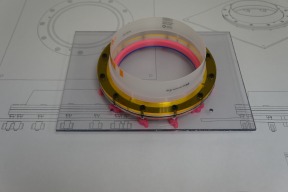
Assembled VAT
I'm happy with this setup and baring any small tweaks I feel like it is complete. I will also be using the OB Floating Nut Plates to attach it to the Top Cover Plate (standard nuts are used in the test sample). Oh yeah, the "test" top plate does not have the main hole in it for the VAT, it's simply was a way to prove I could apply enough tension to the FEP Film.
Lastly, the overall design could still change based on the results of the DLP Projector testing. Samer will be shipping that to me on Monday, so hopefully I'll get to play around with it next weekend and finalize the frame design...it's changed so much, and so often, it will nice to solidify it once and for all...
To be continued...
Update: 4-12-2016My last update indicated that I would be utilizing my "Homedepot Flex VAT", I am sticking to that design, however, nothing is as simple as that. It took a lot of prototype parts, and testing several different configurations to get the final version…but I’m there.
If you just want to see the finished part skip to the photos, if you want to know how I got there continue reading…
V-1
The as illustrated in the previous photos consisted of a few major parts.
HD Bucket Top - Upper Flange – Foam Gaskets – Roast Bag (RB) – Segmented Lower Flange – Hardware – Clamping arms and stand offs.
V-2
Same basic setup I just replaced the clamping arms and stand offs with longer flange bolts that were inserted in the opposite direction of the original flange bolts (sorry no photos). I drilled six (6) additional holes through the Top Plate and used printed PLA Wing Nuts (I tapped these to M5 threads) to create the tension of the RB Sheet. This worked well, although I could still see a bit of oil canning in the flange between the (6) tensions bolts. FYI: I still used M5 nuts on all 12 flange bolts to create a good seal between the VAT and the RB sheet.
V-3
This version simple turned the remaining (6) Flange bolts into Flange/Tension Bolts; they all were now in the same direction and running through the Top Plate. This worked really well and all but eliminated the oil canning in the flange between the bolts. There was one thing I didn’t like about this setup...it was the loose bolts. Even after installing the nuts to seal the FEP sheet you could still twist the screws out when installing the Wing Nuts, so you had to use a hex wrench to keep them in palce. This was corrected in V-4
V-4
I changed (4) things in this version to eliminate the remaining oil canning, loosening bolt issue, the flimsy RB and the lack of tension control.
1: Added an additional Upper Flange, this was 4.5 mm thick and had holes small enough to tap to a M5 thread. I also printed new Wing Nuts using a standard M5 nut in-lieu-of tapping the PLA Wing Nut. These are much easier to get on and off as they will spin much more freely than the tapped version. This combination resolved the bolt loosening issue as the bolts are now threaded into the additional Upper Flange and the Wing Nut spin freely.
2: The additional Upper Flange also resolved the remaining Oil Canning issue as it makes for stronger/stiffer Upper Flange Assembly. I may opt to bond the two upper flanges together at some point, although I do not believe it to be a necessity, it would more for conveyance purposes (less overall parts to deal with).
3. Replaced the Roasting Bag with actual FEP sheet (.005”) thick.
4. For tension control, I added 3mm spacer between the flange nuts and the Top Plate. This both restricts and evenly distributes the tension being applied to the FEP by each bolt. The spacer length can of course be adjusted if needed to apply more or less tension. The final length will be determine during the actual printer calibration process.
After these adjustments the FEP sheet is literally, "Tight as Drum"
At this point I am happy with the VAT setup; here are photos of the final results, it is the setup I will use on the printer. I will of course be replacing the "test" Top Plate with the correct plate that will have a hole for the DLP to project the image through.


When I have time I take a quick video showing the tension on the FEP sheet and maybe a little better view of the inner workings of the VAT as a whole.
To be continued...
MakerSL MSL-6 DLP 3D Printer
Build in 'Resin Style Bots' published by Sonny Lowe, Apr 22, 2016.
This will be a DLP 3D Printer designed around an Openbuilds Frame and rail system. It will be a collaborated effort between myself and Ben Smith. We will be building two prototypes.
-
-
Build Author Sonny Lowe, Find all builds by Sonny Lowe
-
- Loading...
-
Build Details
- Build License:
-
- CC - Attribution - CC BY
Reason for this Build
I wanted to design a DLP Printer that is low cost, easy to build and yields quality printsInspired by


