
This is a place holder for this coming build, gotta start somewhere?
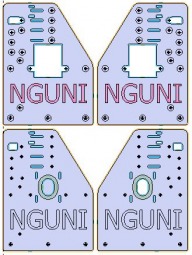
Being in Africa I decided to use an African cattle breed, the Nguni, as the name. Just as with cattle breeders, this OX will self improve over time, the initial version will use MDF plates pretty much everywhere. Later, the machine will cut its own aluminum plates for the upgrades and modifications.
The idea is a pretty standard OX machine, 1000x800 with a slightly higher X rail to allow for 20mm more Z travel. This will allow me to place fuselages or wings directly in the machine for in place machining. However, most of its life it will have a vacuum table inserted as the bed.
The other option that needs the space is a B axis.
The real addition will be a vertical vise on one end. This will allow machining on the end of long things, like wings.
Step 1: make some small parts.
Leadscrew lock collars and motor standoffs. Lock collar are aluminum, standoffs are brass.
The other item is a right angle Allen key for all those Allen head bolts!
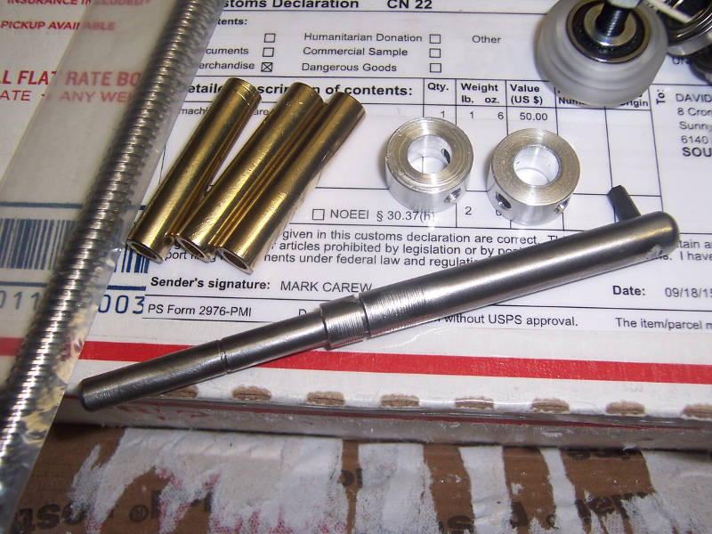
This week I made an extra hex driver. You just cannot buy them in this small town so I took an Allen key, broke it through the angle, and used the short bit for the spanner in the previous photo. Then I made a hex driver with the long part. 10mm square steel bar, some plywood, and make swarf in the lathe.
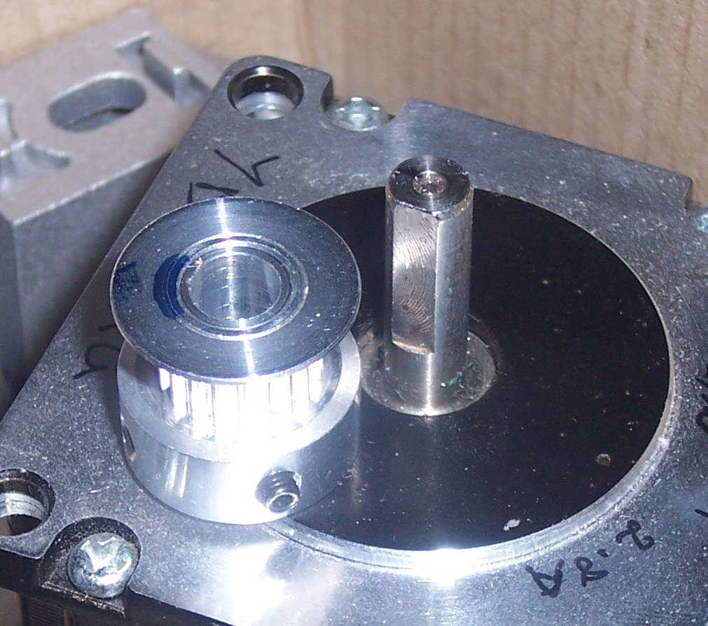
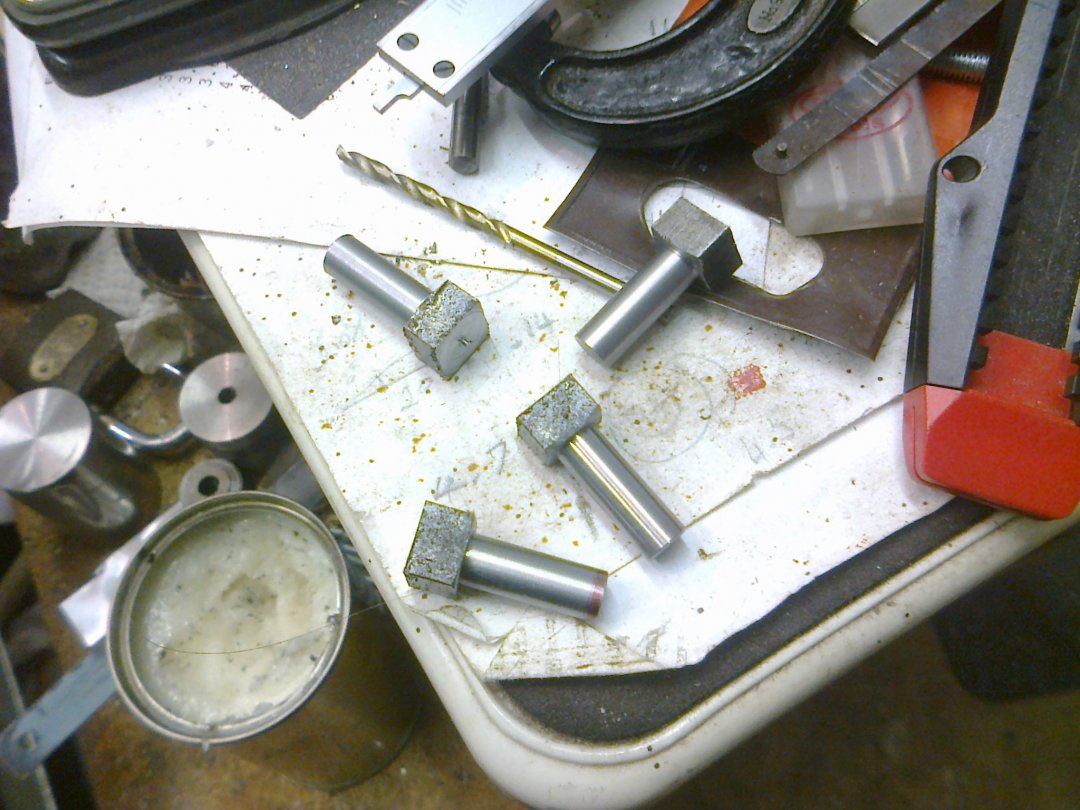
I also made the pulley spacers I need, 3 of them. I purchased pulleys with 8mm bores, not knowing what motor shafts I would get . The NEMA23 motors have 6.35mm shafts so I made precision tubes to fill in the gap and maintain concentricity. They are now Loctited in and one of the grub screws goes through the shim (drilled and tapped) to make contact on the flat of the shaft. In the photo below the shim is the part INSIDE the blue Sharpy mark on the end of the pulley, with a wall thickness of about 0.8mm.
May 2016....
Had to shelve this thing for a while, getting back to it now.
Ordered some Protoneer CNC Shields (V3.0) and had to fix them both, the pin sockets for the motor drivers were soldered at odd angles. Disappointed.
Jul 2016
Finally got some stuff done!
So, progress at last, in among all the household maintenance, car repairs and the daily work, naturally.
- Z axis nut block. My Z leadscrew (M8x8) came with a brass nut that had a lot of backlash. I checked out the Openbuilds antibacklash nut drawings then made a version from aluminum plate. It has a 10mm hole bored in it to take the nut parts. I had to cut my nut in half which required a very narrow parting tool to preserve as much length as possible. I made a less than 0.5mm wide parting tool from a roller cutter blade.
Missing from the images is the M5 bolt for adjusting the backlash.
- Experimental long eccentrics. Since my Z assembly is built from 12mm thick MDF and I have glued it into one piece, I think that the potential exists for the bolts to sit at an angle. I think the heads will catch and remain 'centered' when the eccentrics are adjusted. I have made a couple of experimental long reach eccentrics that reach 20mm into the hole to support the bolt all the way through the plate.
These ones work fine but I did get the heads a little under 6mm and they should match the spacers on the other side so I will make 4 new ones with super accurate heads.
21 July 2016
Got the Z axis assembled and found that the leadscrew is bent. Not amused.
Sept 2o16
Received nice shiny new leadscrew from Openbuilds and completed the Z axis. Decided to rig the motor for a running test.
Test driver: a Big Easy Driver attached to an Arduino running GRBL. The DIP switch soldered to the B.E.D. allows me to set the microstepping. The B.E.D. has pullup resistors that defaults the microstepping to 16x.
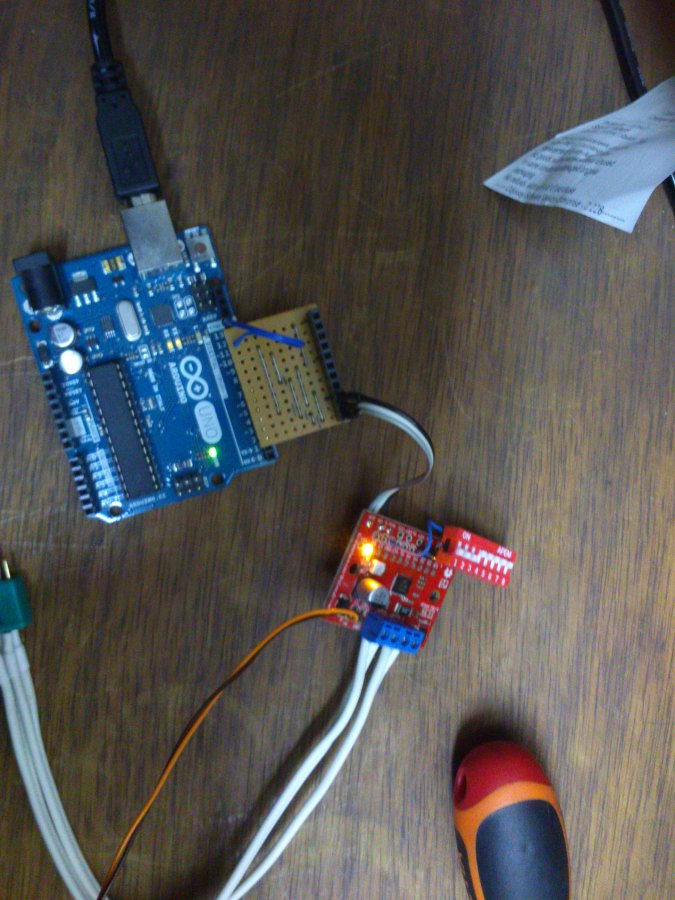
The test run: 4000mm/min unloaded. Reduce to half that when it has to lift its own weight!
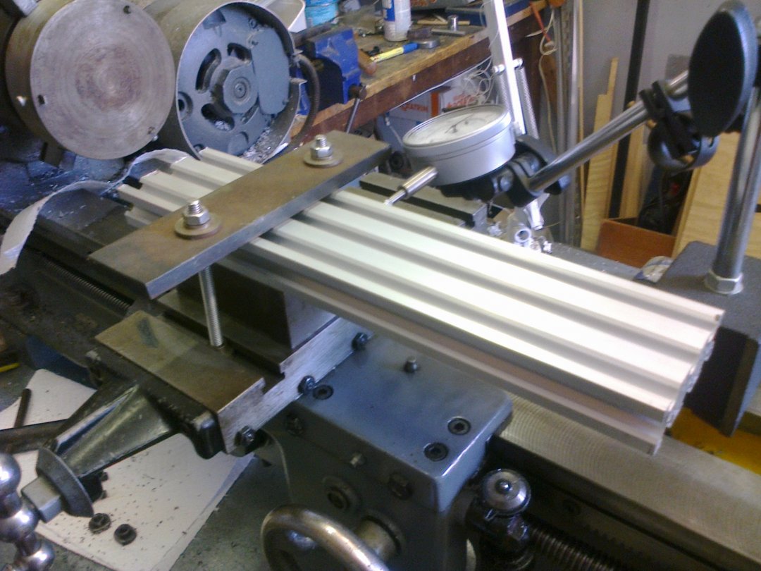
As part of constructing the Z I had to cut off a piece of 20x60 V-slot. Having only a hacksaw I hand cut it then trimmed it square by fly cutting it in my lathe.....
Here it is shown being aligned using the dial indicator to set the side parallel to the ways.
Another part of the Z..... my plates are 12mm MDF and so keeping the bolt heads from digging in is something to watch for. After a trial assembly with stock eccentric nuts I though "those need to be longer to support the bolt all the way through" and these are the result.... 24mm long eccentric nuts.
December 2017
Sigh... time flies by! But, the X gantry is complete, Y rails are trimmed to length, and there is almost enough space for it on the build desk! Watch this space....
On 14 Januray 2018 it cut its first model airplane from foam sheet, pics and video and general ranting to follow.....
The Nguni - an OX variant
Build in 'Cartesian Style CNC' published by David the swarfer, Jan 15, 2018.
A modified OX with more X clearance, MDF plates, vacuum table
-
-
Build Author David the swarfer, Find all builds by David the swarfer
-
- Loading...
-
Build Details
- Build License:
-
- CC - Attribution - CC BY


