
Currently I am running a cheap, acrylic framed, Migbot Prusa i3 printer and although it does what it's designed to do, it's junk. I know, you get what you pay for, but, it got me in the door.
I've spent a lot of time trying to stiffen up the frame, lots of time adjusting belts, lots of time replacing junk parts and warped acrylic. I could spend money on an aluminum i3 frame from a seller on Ebay, but I wanted to make it my own and also use up the pile of parts I've accumulated.
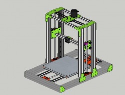
Attached is my design to date, I know the frame is probably a bit over-killed but I want to be sure to eliminate frame movement and vibration. Also, the intent is to mount everything on the frame including two print heads, filament spool, controller and PS. Eventually, there will be a removable enclosure as well but I haven't thought that through yet.
Right now I'm stuck on the Z axis, more specifically, how to power the Z axis screws. Do I use a nema 17 stepper on each Z screw? Or, do I use one nema 23 stepper mounted in the middle and use belts to drive the Z axis screws? (see the attached .skp) The Z axis screws will be the standard acme 8mm Tr8*8-4 found in the OBPS. My concern with the dual 17's is keeping the screws in sync and keeping the X axis level, my current i3 has a real problem with this. If I use the single nema 23, what should the gear ratio be? I'm not looking for speed but more precision...on the other hand, I don't want to wait 20 minutes for the bed to raise up to the print head either.
The X axis will also be screw driven, I was looking into using one of these: http://www.roton.com/Mating_Components.aspx?family=7060998 , in hopes of getting good speed and precision. I've not been able to find much information on using a torque spline screw for this type of application. Any thoughts on this is appreciated.
As far as the Y axis, I haven't decided on belt or screw. I have designs for both but there are pro's and con's to each and I can't make up my mind. If I decide to use a screw then it would probably be a torque spline. One of the downfalls of the screw driven Y axis, IMHO, is where to mount the stepper. Hanging off the back rail (larger footprint) or inside the base frame where I'll lose + Y movement.
Here are a few things I do know because I already have them:
- the controller will be an Azteeg X3 Pro
- power supply will be 24V 800W
-print heads will be all metal J-heads with direct drive filament feed
-print area will be around 300mm x 300mm x 350mm
-will have a 12" x 12" heated build plate topped with 1/4" mic 6 aluminum plate
- the frame will be aluminum extrusion left over from my OX cnc build, except for the "L" profile Z axis rails. These will be ordered from Misumi.
-miscellaneous aluminum brackets/stepper mounts will be cut out of 1/8" 6060 aluminum plate on my OX.
- all other mechanical parts will likely come from the OBPS
Please feel free to comment or critique, I need all the knowledge I can get.
EDIT; I believe my design is finalized. All plates will be G10 as it is easier for me to cut on my OX. The Z axis will be dual screws driven by a single Nema 23 and an endless GT3 belt. The Z screws will be 10 x 2 5 start screws and the X/Y axis will be 10 x 35 28 start screws, both from Helix Linear. Nema 17's will be used on the X/Y axes.
V Rail 3D printer
Build in 'Cartesian Style Bots' published by Josh B, Sep 24, 2015.
My version a Cartesian style 3d printer, an attempt to eliminate frame vibration and movement and to use up materials left over from other projects.
-
-
Build Author Josh B, Find all builds by Josh B
-
- Loading...
-
Build Details
- Build License:
-
- CC - Attribution Share Alike - CC BY SA