
*Update (05/19/17): Added Voxel OX 8" parts list spreadsheet*
Voxel OX 3D printer and CNC platform
Built by Marshall Peck (and some awesome friends) in Austin, TX - Primary build page located here.
Significant contributions, testing, and suggestions by thehans
thehans | OpenBuilds
See the discussions page for comments, questions and lots of awesome Voxel OX builds by people from all over.
Han's build:
Easy to domesticate!
Voxel OXen ready to join a team:
10/3/2015 update
- Extruder Body more accessible (Dropbox STEP and STL files updated)
- Added more firmware links to description
- CNC milling trials coming soon!
- Cura and slicer profiles soon as well.
Intro
Voxel OX is a super-sturdy 3D printer and CNC platform design I came up with for our 3D printing shop. It uses mostly 20x80 v-slot extrusion, is pleasantly quick to build, and rigid enough to hold a 400w spindle. We've completed over half a dozen variations of this build. Print quality and reliability have turned out to be excellent and dependable.
A couple short 20x20mm extrusions make the universal extruder mount that can be used to mount cooling fans and various accessories. STEP files for a Greg's wade extruder variation, RAMPS & LCD mount, adjustable Y-idler and 3D printable rubber (TPU) dampening feet included in the assembly, could be used in other builds. Some parts might be missing or will be updated soon (message if you need them sooner).
Basic assembly instructions:
Some of the cut lengths can be determined AFTER setting up the x-axis first and using it to line up your Z-axis rails. The steps for this are as follows:
1) Cut the x-axis and z-rails to you desired length using a chop saw with metal/steel/aluminum cutting blade. A carpenter's square should be used to adjust your chop saw. Cutting thin slices of scrap or excess could be used for this.
**Tip** Cut pieces an inch or more longer than necessary in case of mistakes
**Tip** Cut z-axis rails together to get identical lengths
**Tip** Chamfer / file extrusion v-wheel entry slots to prevent knicks on the wheels, check for imperfections on extrusion used for linear axis.
2) Assemble the x-axis and it's wheel carriages. The x-axis rail has 2 holes on each side tapped with an M5 tap for the the non-eccentric side of the carriage plates.
2) With frame laying down, insert both z-axis wheels with eccentric nuts. (Slot/Dot on eccentric nut points away from rail for max loosening.
3) With the z-axis rails seated in the carriages attached to the x-axis, tighten the eccentric nuts until the rails are firm, not loose and not over tight such that gravity cannot overcome the wheels.
4) The x-axis and z-frame laying down can now be used to check your top and bottom frame lengths and to check again to see if your cuts are mostly square. This also helps hold the z-rails for assembly of the top and bottom frame.
**Tip** Load necessary t-nuts and assemble x-carriage slide it on the x-axis rail first to prevent re-assembly later.
**Tip** The frame assembly is somewhat forgiving to non-perfect cuts. The y-axis doesn't need to have straight ends at all, for example. Leave most of the corner brackets somewhat loose until final assembly. When the z-axis, top and bottom frame are assembled, manually move the x-gantry (z-axis) up and down, loosen then tighten the cast brackets so that it is not difficult to move in one area or another. This technique can also be used when lining up the z-motor mounts and lead screw nuts.
X belt assembly
Running belt for X and Y axis can be a little tricky. The following method, calls for twisting the belt around the idler in both cases. This allows for smoother motion. The exact order of operations allows for easy looping and threading through the slots.
Step 1) Thread entire belt through right side of the plate (bottom slot) and around the back of the motor pulley with teeth facing the direction shown below.
(fig. 1)
![[IMG]](proxy.php?image=http%3A%2F%2Fi.imgur.com%2FSYTENNE.jpg&hash=fac8d0aa1eb7acd4c88a7bbe5511c495)
Step 2)
Run the belt over, then under the idler. There should be a belt twist in-between the motor pulley and the idler.
Next, push the belt through the slot (teeth facing left) into the slot and under the plate. The carriage can be moved to the left slightly to help push the belt out.
(fig. 2)
Step 3)
Move either the motor mount or idler to give about 1cm of slack. Next, zip tie the ends of the belt so that the teeth touch each other. 3 zip ties should be enough to secure the belt. Clip the excess.
(fig.3)
(fig. 4)
***More assembly tips, documentation, calibration and pics to be added later.
Feel free to ask, comment critique or try the build.***
Firmware
The Arduino/RAMPS uses generic Marlin firmware. Of course, others could be used.
Here's an Auto-leveling Instructable I wrote containing sensor and setup recommendations and some firmware related info for Marlin. Here's the link for the latest firmware for 10" x10"16" (auto-leveling enabled) version of Marlin I'm using. Edits for max travel / machine size and other minute changes might be needed for your setup.
Features and Stuff
If you would like a head start with the build, we have stocked enough extra parts from OpenBuilds as distributors to have a small inventory of pre-cut pieces, assembled frames or complete machines in various sizes. For more info, you can send us a message here, contact via prototobuilds.com , ProtoBuilds or email [email protected]
This design is easily extendable by changing a small number of parts. Want it 16in tall? Just change the (2) z-axis rails and add (2) longer lead screws. Want the y-axis longer? (1) rail and longer belt is all that's required. The x-axis can be extended by changing the top and bottom frame, x-axis rail (3 pieces) and longer belt.
So far we made a few different sizes and one that used 1000mm long rails and lead screw for a sky-scraper like machine which seems close to the practical limit for height using this design. The 16" tall version using 500mm lead screw turns out very rigid.
For complete assembly, containing part lists and sub-assemblies downloadable in multiple formats including Autodesk, SolidWorks, STEP/IGES and Fusion 360 use the following link:
Full Assembly (View only, use the dropbox STEP file assembly below for download)
Assembly made using Fusion 360 (free for Individuals, Startups, and Students).
Voxel OX 8" BOM:
Voxel OX 8" - parts list
Voxel OX 3D Printable Files (STEP and STL):
Dropbox - Voxel Ox 3D Printable Parts
Dropbox- .STEP full assembly
Extruder sub-assembly BOM:
Marshall's Greg's Wade Extruder on Thingiverse
Marshall's Greg's Wade Extruder BOM
The community here has been a huge inspiration. And of course, Open builds has done an excellent job making high quality linear components. Hope you enjoy the project.
Features:
As Built:
- 20mm x 80mm and 20mm x 60mm black V-Slot frame
- Variable build area
- Up to 75mm/s print speed and up to 200mm/s travel speed
- Lead screw driven Z axis
- Belt driven X and Y axis
- Adjustable Y axis tensioner
- Each axis expandable up to maximum OpenBuilds extrusion profiles and available lead screw.
- Auto-leveling
- Heavy duty frame
- Mounts any Greg's wade extruder (custom Wade's STEP files included)
- Mount option for 400w spindle
- Any axis dimension ranging 8", 10", 12" or 16" x/y/z (8x8x8" in most pictures)
- E3D V6 Hotend, E3D Volcano, or Generic J-head compatible
- 76oz-in high torque NEMA 17 stepper motors
- Electronics:
- Ramps +LCD and Arduino kit
- drv8825 drivers (for more current over A4988 Pololu)
- Mechanical X/Y Endstops
- 12v 30a power supply
- Inductive sensor
![[IMG]](proxy.php?image=http%3A%2F%2Fi.imgur.com%2FONQ9AIu.jpg&hash=ff6fadf76359c2237168cb354d43d879)
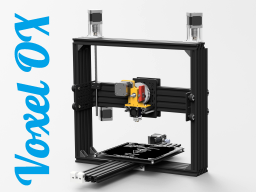
Voxel OX - Extendable 3D Printer and CNC Platform
Build in 'Cartesian Style Bots' published by Marshall Peck, May 25, 2017.
An open source 3D printer design with a sturdy V-Slot frame
-
-
Build Author Marshall Peck, Find all builds by Marshall Peck
-
- Loading...
![[IMG]](proxy.php?image=http%3A%2F%2Fi.imgur.com%2F2hjkVLT.png&hash=c22e2350742bddd9de70b05f2fdf0b58)
![[IMG]](proxy.php?image=https%3A%2F%2Fscontent.fmkc1-1.fna.fbcdn.net%2Fv%2Ft31.0-8%2F12513986_1021002474602917_6490757722833156752_o.jpg%3Foh%3D0f989083f830cfa2f5361654ede7e665%26oe%3D596D675E&hash=9fe356e02eaf294475f5d5dc8a0540f8)
![[IMG]](proxy.php?image=https%3A%2F%2Fscontent.fmkc1-1.fna.fbcdn.net%2Fv%2Ft31.0-8%2F15731886_10102816434315195_6288502573357871892_o.jpg%3Foh%3D00b8ce70463012760792272c5ad19a91%26oe%3D59684D99&hash=89d1a1e5c697d7304c87087e87c47aa3)
![[IMG]](proxy.php?image=http%3A%2F%2Fi.imgur.com%2Fj3XRK6o.jpg&hash=d7ce97199865cc539181aea1b7a57611)
![[IMG]](proxy.php?image=http%3A%2F%2Fi.imgur.com%2FmqeCHfG.jpg&hash=947664ea60f5457984e1ad4a02f5fbf1)
![[IMG]](proxy.php?image=http%3A%2F%2Fi.imgur.com%2FIHCFsx5.jpg&hash=cbf3a3bc8c5e8da0e8efc89e24ce83eb)
![[IMG]](proxy.php?image=http%3A%2F%2Fi.imgur.com%2FrNSFjD3.jpg&hash=c4daafaa5dd8f1e3fa6452d8641a8eb9)
![[IMG]](proxy.php?image=http%3A%2F%2Fi.imgur.com%2FbuCJ3ok.png&hash=86ca6ba16b7e8a7d4436f757727f98e3)
![[IMG]](proxy.php?image=http%3A%2F%2Fi.imgur.com%2Fp2IEWfO.jpg&hash=fd9662a2dba17ed09b2c1c19abe31dd3)
![[IMG]](proxy.php?image=http%3A%2F%2Fi.imgur.com%2Fs3RQzmD.jpg&hash=0b579b91eb11269f5ae27db7a858ee89)
![[IMG]](proxy.php?image=http%3A%2F%2Fi.imgur.com%2F8RKDo7i.jpg&hash=7db222b8b6e3d7b9c21a0f5445d74a00)
![[IMG]](proxy.php?image=http%3A%2F%2Fi.imgur.com%2FjKW0jNh.png&hash=9a876cab3acb5305df17a9bfff153e00)
![[IMG]](proxy.php?image=http%3A%2F%2Fi.imgur.com%2FQ9Uud5B.jpg&hash=a525b7ae13700f13b9379f6de9226fc7)
![[IMG]](proxy.php?image=http%3A%2F%2Fi.imgur.com%2FwUZuFYy.jpg&hash=41e6947db529bb8089717119a2a10197)
![[IMG]](proxy.php?image=http%3A%2F%2Fi.imgur.com%2FgaS6X0a.jpg&hash=6db9abda2f21acc3dc4e1a73ac845f6d)