Welcome to Our Community

Some features disabled for guests. Register Today.

C-Beam Machine XL

Discussion in 'CNC Mills/Routers' started by PhotoSgt85, Nov 18, 2016.
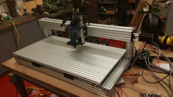
  1. PhotoSgt85

    PhotoSgt85 Well-Known
    Builder

    Joined:
    Jul 27, 2015
    Messages:
    54
    Likes Received:
    66
    PhotoSgt85 published a new build:

    Read more about this build...
     
    Moag likes this.
  2. PhotoSgt85

    PhotoSgt85 Well-Known
    Builder

    Joined:
    Jul 27, 2015
    Messages:
    54
    Likes Received:
    66
    20161208_083229.jpg
     
  3. PhotoSgt85

    PhotoSgt85 Well-Known
    Builder

    Joined:
    Jul 27, 2015
    Messages:
    54
    Likes Received:
    66
    So I have mechanically completed the build (this is at work so I can work on it in spurts). Just have to complete the wiring of the stepper drivers, power supply and work on setting up the smoothie board. I have the spoiler boards (not shown) but am considering pursuing a different type of spoiler board because there are some tools that can induce moisture in the area and I really don't want to be replacing MDF constantly.
     
    GrayUK and Mark Carew like this.
  4. jamesdjadams

    jamesdjadams Well-Known
    Builder

    Joined:
    Nov 1, 2016
    Messages:
    40
    Likes Received:
    48
    Hi PhotoSgt85, I'm interested in using something other than MDF for a base-plate as well. Aluminum would be ideal but pricey. Have you had any ideas for an alternative?
     
  5. PhotoSgt85

    PhotoSgt85 Well-Known
    Builder

    Joined:
    Jul 27, 2015
    Messages:
    54
    Likes Received:
    66
    My thoughts are to have a permanent aluminum base (either V-slot or just a plate of 1/4 or so inch plate. On this would be mounted a HDPE spoiler board. I have to look into it more but there is an Open Source recycling system called Precious Plastics that I would really like to utilize in general, and this would allow me to reuse spoiler boards as they are cut into. Recycling used 3D printer filament would also be optimal since we print a lot here for experiments. Basically I want to build an ecosystem in which I am capable of extremely efficient with materials and reusing what I can. This may not be for everyone, but I just keep looking at all the milk jugs and cat litter containers I am trowing in a recycling bin that I could be using productively. My XL will be almost exclusively used for aluminum and will be tried to be used for some sheet steel (front of 19" rack mounts), so I wanted a dimensionally stable spoiler with minimum moisture sensitivity as I will eventually add coolant flow.
     
    jamesdjadams likes this.
  6. jamesdjadams

    jamesdjadams Well-Known
    Builder

    Joined:
    Nov 1, 2016
    Messages:
    40
    Likes Received:
    48
    Very interesting. Thank for sharing.
     
  7. jamesdjadams

    jamesdjadams Well-Known
    Builder

    Joined:
    Nov 1, 2016
    Messages:
    40
    Likes Received:
    48
    I decided to go with aluminum too.
     

    Attached Files:

    PhotoSgt85 likes this.
  8. PhotoSgt85

    PhotoSgt85 Well-Known
    Builder

    Joined:
    Jul 27, 2015
    Messages:
    54
    Likes Received:
    66
    I love the look of an aluminum bed on these machines. Awesome jamesdjadams!
     
  9. jamesdjadams

    jamesdjadams Well-Known
    Builder

    Joined:
    Nov 1, 2016
    Messages:
    40
    Likes Received:
    48
  10. Rick 2.0

    Rick 2.0 OpenBuilds Team
    Staff Member Moderator Builder Resident Builder

    Joined:
    Dec 20, 2013
    Messages:
    2,852
    Likes Received:
    1,524
    That's what, like $6 US? ;)
     
  11. jamesdjadams

    jamesdjadams Well-Known
    Builder

    Joined:
    Nov 1, 2016
    Messages:
    40
    Likes Received:
    48
    #11 jamesdjadams, Jan 20, 2017
    Last edited: Jan 20, 2017
    Rick 2.0 likes this.
  12. Sonny Lowe

    Sonny Lowe Journeyman
    Staff Member Builder Resident Builder

    Joined:
    Nov 11, 2015
    Messages:
    143
    Likes Received:
    157
    I use HDPE in my small mill, love it!!! It's a bit pricey in the size you need though :eek: But you could make some cool stuff out of the leftovers ;)

    HDPE 1/2" x 24" x 36"
     
    jamesdjadams likes this.
  13. jamesdjadams

    jamesdjadams Well-Known
    Builder

    Joined:
    Nov 1, 2016
    Messages:
    40
    Likes Received:
    48
    Does it flex very much? I really don't know anything about HDPE. Based on the URL, it seems like strong stuff.
     
    PhotoSgt85 likes this.
  14. PhotoSgt85

    PhotoSgt85 Well-Known
    Builder

    Joined:
    Jul 27, 2015
    Messages:
    54
    Likes Received:
    66
    I have plans for a HDPE spoiler board on my aluminum (vslot) bed. The best part is that after you cut into it a few times you can recycle it into another spoiler board. The recycling part will be a whole other projects though.
     
    Sonny Lowe and jamesdjadams like this.
  15. Sonny Lowe

    Sonny Lowe Journeyman
    Staff Member Builder Resident Builder

    Joined:
    Nov 11, 2015
    Messages:
    143
    Likes Received:
    157
    It is pretty darn rigid, and I think at 1/2" thick you wouldn't see much if any flex. I have a piece 1" x 12" x 12" and I could stand on it and not see it bend, but of coarse 1/2" wouldn't withstand that much. I might have something similar at work, if so I'll see if I can bend or flex it by hand. What's the longest spread between supports on the XL?
     
    #15 Sonny Lowe, Jan 26, 2017
    Last edited: Jan 27, 2017
  16. PhotoSgt85

    PhotoSgt85 Well-Known
    Builder

    Joined:
    Jul 27, 2015
    Messages:
    54
    Likes Received:
    66
    for the forces that the CBeam XL should see in the z axis I cant imagine 1/2" HDPE flexing any discernible amount.
     
    jamesdjadams likes this.
  17. PhotoSgt85

    PhotoSgt85 Well-Known
    Builder

    Joined:
    Jul 27, 2015
    Messages:
    54
    Likes Received:
    66
    Has anyone else had any issues with their X axis carriage loosening during cuts? I have been cutting plates that take about an hour each and when im done there is a lot of slop in the x carriage. When I punch through a material into the spoil board i get this bouncing that ruins my surface finish and in a few cases my whole part. Anyone else have this issue and what are your solutions?
     
  18. jamesdjadams

    jamesdjadams Well-Known
    Builder

    Joined:
    Nov 1, 2016
    Messages:
    40
    Likes Received:
    48
    I am having a similar problem with the loosening.
     
  19. Giarc

    Giarc OpenBuilds Team
    Staff Member Moderator Builder Resident Builder

    Joined:
    Jan 24, 2015
    Messages:
    2,892
    Likes Received:
    1,610
    Have you guys tried locktite? Or are you referring to the screws running through the wheels loosening? I used locktite when I assembled mine a year ago and it is still tight. However, when screwing the gantry plates to the X axis beam, I used 25 mm M5 screws vs. the 15 mm.
     
  20. PhotoSgt85

    PhotoSgt85 Well-Known
    Builder

    Joined:
    Jul 27, 2015
    Messages:
    54
    Likes Received:
    66
    My problem is the eccentrics loosening. I've been working on a full redesign of the z but the issue is really those ecentrics. I hesitate to locktire the nuts as if it doesn't solve the issue I don't want to have to mess with getting it off.
     
  21. Giarc

    Giarc OpenBuilds Team
    Staff Member Moderator Builder Resident Builder

    Joined:
    Jan 24, 2015
    Messages:
    2,892
    Likes Received:
    1,610
    Mine occasionally loosen, as well.
     
  22. PhotoSgt85

    PhotoSgt85 Well-Known
    Builder

    Joined:
    Jul 27, 2015
    Messages:
    54
    Likes Received:
    66
    So in looking at the mechanics involved I have an idea for how to possible minimize this issue: flip the X axis carriage. If you take into account what is loosening and its location (the front bottom eccentrics) and look at it through the lens of a statics problem with the reactionary force from the work piece you will see that the front bottom wheels see the most force on them due to the direction of the torque and the distance to the line of action for the force. While most may not be familiar in academic terms the length of a moment arm (think of a breaker bar vs a normal sized ratchet) changed the force needed to generate the same torque, or in this case resist it. The upper rear wheels see a lower force for two reasons: the front lower wheels become the pivot point around which the carriage wants to rotate and their relative distance to the force. The relative distance part is easy to see, they are farther away from the line of action of the force and therefore resist the force with less stress being developed. The other part is that when the carriage tries to rotate some of the force is exerted along the tangent line formed by the circle with a radius from the pivot point through the point of contact of the upper wheel. This means that the force that could turn the eccentric nut could be resolved into two forces , a thrust load which the threads of the bolt will resist and a downward force equal to F * Sin(Θ) where Θ is the angle of incidence of the force. Conversely the thrust load would be F* Cos(Θ). So this makes sense but the proof is in the pudding, therefore I will have to wait and see how it works after I change the carriage around. I haven't looked at the plates yet to ensure that doing so wont mess something else up but I think it should be OK.
    -PhotoSgt85
     
  23. PhotoSgt85

    PhotoSgt85 Well-Known
    Builder

    Joined:
    Jul 27, 2015
    Messages:
    54
    Likes Received:
    66
    Figured since I took a swag at some signage I should post them up. These were cut on my CBeam XL. Not bad for a first go.
     

    Attached Files:

Share This Page

  1. This site uses cookies to help personalise content, tailor your experience and to keep you logged in if you register.
    By continuing to use this site, you are consenting to our use of cookies.
    Dismiss Notice