Welcome to Our Community

Some features disabled for guests. Register Today.

CraneBot

Discussion in '3D printers' started by runninfarmer, Mar 2, 2015.
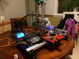
  1. runninfarmer

    runninfarmer Well-Known
    Builder

    Joined:
    Feb 22, 2015
    Messages:
    99
    Likes Received:
    48
    runninfarmer published a new build:

    Read more about this build...
     
  2. Keith Davis

    Keith Davis Veteran
    Builder

    Joined:
    Dec 11, 2013
    Messages:
    506
    Likes Received:
    393
    Quick build, minimum parts, you have that nailed!!! Your simple CraneBot makes a Bukito look like it was designed at the sausage factory.

    I'd like to see your math for deciding to use the geared stepper for the Z axis. I have a Fabbster that uses belts w/16 step motors w/no problem.

    If you want, you can marry two 20x40 Openbuilds extrusions to make a 40x40. This image shows how I make an L shape with a 20x20 & 20x40 but it would also make a 40x40
    [​IMG]
     
    MaryD likes this.
  3. runninfarmer

    runninfarmer Well-Known
    Builder

    Joined:
    Feb 22, 2015
    Messages:
    99
    Likes Received:
    48
    Hi Keith, thanks for the kind words! A normal Nema17 would definitely work well for the Z-axis, the only reason I chose a geared motor was to prevent carriage drop when the motor is not powered. I had that problem with a belt drive I implemented on an Ord bot. The PG35L's are also not too much, ~$25 USD. I like your idea of marrying 20x40's! That would narrow it down to only one type of extrusion needed.
     
  4. Keith Davis

    Keith Davis Veteran
    Builder

    Joined:
    Dec 11, 2013
    Messages:
    506
    Likes Received:
    393
    Ah, I see your point about carriage drop. When that's happened with my Fabbster it was due to power loss and the object was ruined anyhow so dropping the nozzle into it was minor.

    I've tried similar crane designs. I've found that the 45 degree brackets will swivel on the rail to release tension if enough pressure is exerted on the x carriage. To add strength against that, I placed a 2 Hole Joining Strip Plate between the two 45 degree brackets and cranked it tight to the rail. The Joint is 18x40 so it gives a 40mm wall for both brackets to cam against, preventing movement - and guarantees their squareness and 40mm positioning for assembly. http://openbuildspartstore.com/2-hole-joining-strip-plate/
     
  5. runninfarmer

    runninfarmer Well-Known
    Builder

    Joined:
    Feb 22, 2015
    Messages:
    99
    Likes Received:
    48
    I think I was having the problem you mentioned. I found it was terribly hard to get the black brackets holding my wheels tight against the v-slot. I ended up making a 59.7mm hole spacing plate for the brackets on my z-axis carriage plate. When factoring in costs for those brackets vs using a gantry plate, for a couple dollars more the gantry plate would probably work better.


    IMG_0804.JPG
     
  6. Keith Davis

    Keith Davis Veteran
    Builder

    Joined:
    Dec 11, 2013
    Messages:
    506
    Likes Received:
    393
    The gantry plate is the excellent way to go (if you don't mind the swiss cheese of the extra holes). Your plastic would not give you a good hole for the eccentric nuts to cam in.

    Here's something to consider, and why I mentioned the Bukito. Deezmaker pioneered a concept with their single rail z axis Bukito - the three wheel Z axis. Consider that with 4 wheels you are tightening two wheels against two opposite wheels. If the resulting tension against all 4 wheel are not exactly identical it will effect the end of your crane and it's trueness to the frame (as much ax 2mm on the far end). With 3 wheels, and the eccentric being the lone wheel, tightening that wheel only evenly tensions all 3 wheels and automatically trues the x axis with the z axis. And, a triangle is stronger than a 4 sided box.

    That said, the gantry plate is already set up for that, sort of. If you use the plate horizontally instead of vertically, there is a center eccentric size hole spaced right for a 40mm z rail. The 1.65mm head of that center bolt creates a problem in that it is in the center of your x axis rail, but shimming your x axis rail 2mm away from the gantry plate with 2 hardware store 5mm fender washers will give clearance.

    Anyhow, once you get the gantry plate, play with both the 4 & 3 wheel concepts.
     
  7. runninfarmer

    runninfarmer Well-Known
    Builder

    Joined:
    Feb 22, 2015
    Messages:
    99
    Likes Received:
    48
    Got some work done on some new carriage plates. Since I don't have access to a CNC mill or waterjet, had to get creative and print off drill templates with the ol' HP inkjet. I taped them to some 3"x4"x 1/8" aluminum blanks and used a center punch for the holes. Then I used a harbor freight drill press to drill them. I was surprised at how well they worked. The wheels cammed well to the v-slot. I'm testing some weight limits with a Nema17 extruder directly bolted to the carriage.

    IMG_0837[1].JPG

    IMG_0838[1].JPG

    IMG_0839[1].JPG

    IMG_0840[1].JPG

    IMG_0841[1].JPG

    IMG_0843[1].JPG

    IMG_0844[1].JPG


    I've tried a triangle wheel pattern, and I've found there's just too much play with it so I'm sticking with 4 wheels for all my carriages for now. The direct drive extruder may prove to be too heavy and I might have to go with a bowden setup.
     

    Attached Files:

    #7 runninfarmer, Mar 9, 2015
    Last edited: Mar 9, 2015
  8. runninfarmer

    runninfarmer Well-Known
    Builder

    Joined:
    Feb 22, 2015
    Messages:
    99
    Likes Received:
    48
    Got my RAMPs board mounted and also redesigned my z-axis belt system. Made it more streamline by adding an additional plate to the carriage. I need to space the holes better for better belt paths, but for now this will suffice. I'm hoping to do some movement tests this weekend.

    image.jpg image.jpg
     
  9. runninfarmer

    runninfarmer Well-Known
    Builder

    Joined:
    Feb 22, 2015
    Messages:
    99
    Likes Received:
    48
    Got the electronics wired and is working great. Most quiet printer I've ever built. Will get it pronting soon. Here's a video of first tests :
    :


    image.jpg
     
  10. runninfarmer

    runninfarmer Well-Known
    Builder

    Joined:
    Feb 22, 2015
    Messages:
    99
    Likes Received:
    48
    It's finally printing! I'm pretty pleased with it. Need to do some fine tuning but it's running well. Here's a video of it printing:


    image.jpg

    image.jpg
     
  11. Keith Davis

    Keith Davis Veteran
    Builder

    Joined:
    Dec 11, 2013
    Messages:
    506
    Likes Received:
    393
    Looks great.
    What kind of speed are you getting? The vid looks like it's probably moving 100 m/sec.
     
  12. runninfarmer

    runninfarmer Well-Known
    Builder

    Joined:
    Feb 22, 2015
    Messages:
    99
    Likes Received:
    48
    Hi Keith, thanks! For that print my print speed was 40 mm/s, outer perimter 35mm/s, and infill at 70 mm/s. Had it printing decent, transported it to Midwest Reprap fest, and then it didn't print worth a darn, lol. Had some z-axis issues, either loose hotend, low torque motor, or combination of the two. The PGL-048 should technically have enough torque, but the driver has to be turned down so low or those motors burn up. May need to change to Nema17 and leadscrew.
     
    #12 runninfarmer, Mar 22, 2015
    Last edited: Mar 22, 2015
  13. Buzz_2010

    Buzz_2010 New
    Builder

    Joined:
    Mar 16, 2015
    Messages:
    1
    Likes Received:
    0
    Looking good hows your z-axis issue ? How stable is the arm when printing at high speed ? I am currently building a printer which is similar to yours i should have my frame built next week and will post it here. I am not using v-rail as i have sections of bosch extrution so i will be making all my own wheels.
     
  14. runninfarmer

    runninfarmer Well-Known
    Builder

    Joined:
    Feb 22, 2015
    Messages:
    99
    Likes Received:
    48
    Hi Buzz_2010, thanks for the compliment. I changed the z-axis over to leadscrew and will post an updated pic later. The tower itself is pretty stable. If you move the carriage by hand it can cause some tilt in the y axis, but y-axis movements are fine, even while accelerating. I found my problems were with the PG35L motor stalling on me and a lose hotend holder. The combo of those problems was causing a dragging print head.

    I like belt-driven z axes, but keeping good belt tension is a huge weakness. That's why I switched it over to leadscrew.

    Will look forward to seeing your build!
     
    #14 runninfarmer, Apr 2, 2015
    Last edited: Apr 2, 2015
  15. Keith Davis

    Keith Davis Veteran
    Builder

    Joined:
    Dec 11, 2013
    Messages:
    506
    Likes Received:
    393
    Howdy running farmer :) I'm working on a 1 arm bandit now.

    I kinda figured you might have problems with a PG35L not being powerful enough. That's a major speed reduction/power increase. I abandoned the idea of using belts because of the math. Consider, a 16 step motor would move a belt 1 tooth per step if you had a 16 tooth pulley. That's a 2mm Z movement. Even a 32 step motor would deliver a 1mm Z movement. For the same reason, I will never use an acme screw for a Z axis. An acme screw moves 8mm per revolution. With 16 steps that makes a minimum Z movement of .5mm, hardly a fine resolution. Josef Prusa went to using a 5mm threaded rod for a reason, it gives 10 times finer resolution over an acme screw - one revolution = .8mm, one step = .05mm. For fine tuning of first layer height an acme screw can't even get into the ball park.

    Here are photos of where I'm at. I need to add the psu behind the upright beam, and a ramps board below the psu mounted on the bottom frame pate. I'm using the new C-Beam concept on the Z axis by bolting two 20x20 rails to a 20x80 rail, then running a mini v-wheel kit on each 20x20 with the 5mm rod up the channel. To reduce height, I invert the Z motor and run the Z rod with a belt. I had a 208 belt so that's what I used. I have a 132 belt arriving next week and will use it instead. I'm very pleased with how stable this is using the two mini v-wheel kits for the Z.

    [​IMG] [​IMG]

    [​IMG] [​IMG]

    [​IMG]
     
  16. runninfarmer

    runninfarmer Well-Known
    Builder

    Joined:
    Feb 22, 2015
    Messages:
    99
    Likes Received:
    48
    Good lookin design Keith! The simplicity of 1 arm machines is too attractive to pass up! Glad you're trying the C-beam concept, I'd like to use it too at some point.

    I use 20 tooth GT2 pulleys and actually get plenty of resolution for Z axis. With that pulley and 1/16th stepping (1.8 deg motor) it's 80 steps/mm or 0.0125 mm/step. Most people will never print 0.01 mm layers, even 0.1mm is not really needed.

    My current leadscrew has 1" travel per revolution. With 1.8 degree motor and 1/16 stepping that has 0.009 mm/step. So on both setups I have great resolution, just glad I don't have tension problems anymore. You're also right I'm glad I have bigger stepper now for Z-axis.
     
    #16 runninfarmer, Apr 2, 2015
    Last edited: Apr 2, 2015
  17. DarkAlchemist

    DarkAlchemist Well-Known
    Builder

    Joined:
    Aug 2, 2014
    Messages:
    401
    Likes Received:
    22
    Have a bom by chance?
     
  18. runninfarmer

    runninfarmer Well-Known
    Builder

    Joined:
    Feb 22, 2015
    Messages:
    99
    Likes Received:
    48
    I don't have one written up, but here's the specs on the parts:

    QTY Part
    2 2"x2"x 12" T-slot
    1 2" x 2" x 24" T-slot
    2 2" x 2" 4 hole 80/20 inc L bracket
    2 500 mm 2040 V-slot
    1 24" 2040 V-slot
    3 1/8" Aluminum Carriage Plates
    1 Openbuilds build plate
    12 Solid V-wheel kits
    6 eccentric spacers
    2 (3) Idler pulleys, 3 if using belt drivenz-axis
    8 45 Degree corner bracket
    4 Nema17
    1 MK2 Heated bed
    1 RAMPs 1.4 with Mega 2560

    I need to check on the dimensions of the cap screws I used. Printed parts are on my thingiverse page here: http://www.thingiverse.com/thing:731785
     
  19. DarkAlchemist

    DarkAlchemist Well-Known
    Builder

    Joined:
    Aug 2, 2014
    Messages:
    401
    Likes Received:
    22
    I wish we could get all of that in one source (meaning the extrusions) though I believe I would try as I try and force myself (yes, in the USA that is painful most times) to be metric on these things. Not really sure how you mesh up the V-Slot metric and the Imperial T-slot, and 80/20, though.
     
  20. runninfarmer

    runninfarmer Well-Known
    Builder

    Joined:
    Feb 22, 2015
    Messages:
    99
    Likes Received:
    48
    Actually, since openbuilds just came out with 40mm x 40mm V-slot, that would be a perfect subsititute for the 2"x2" extrusion. I just had that lying around, that's why I used that. Misumi also has 1/8" stainless steel L brackets specifically for 20mm series 40 x40 T-slot, which would work on the V-slot. Link for Misumi: http://us.misumi-ec.com/vona2/detail/110302246060/?KWSearch=shptbdw5&catalogType=00000046871

    I'm using that on my next build since I want to try out the 40x40 v-slot.
     
  21. DarkAlchemist

    DarkAlchemist Well-Known
    Builder

    Joined:
    Aug 2, 2014
    Messages:
    401
    Likes Received:
    22
    I love Misumi (I use their double thick Chrome rods on my printer) and I need Stainless or it will rust here in under two weeks (surface rust that gets worse).
     
  22. Patrick Walls

    Builder

    Joined:
    Dec 30, 2013
    Messages:
    22
    Likes Received:
    1
    runninfarmer,
    just curious, what was your gear reduction on those motors?
    Thanks
    Pat
     
  23. runninfarmer

    runninfarmer Well-Known
    Builder

    Joined:
    Feb 22, 2015
    Messages:
    99
    Likes Received:
    48
  24. Patrick Walls

    Builder

    Joined:
    Dec 30, 2013
    Messages:
    22
    Likes Received:
    1
    I forgot to mention how much I liked your CraneBot 3D printer. It looks like the perfect printer for a new person to try out 3D printing with. You don't end up with a ton of money invested in it and it appears to be relatively simple to work with. I have a load of 8020 15 series and looking at all the 3D stuff being made the 15 series is just out the door. Again, great idea there, I may try it.
     
  25. runninfarmer

    runninfarmer Well-Known
    Builder

    Joined:
    Feb 22, 2015
    Messages:
    99
    Likes Received:
    48
    Hi Patrick, thanks for the compliment! That was a large part of the motivation for this build. I wanted something affordable that could be put together fast (~1-2 hrs), and also easy to calibrate.
     
  26. DarkAlchemist

    DarkAlchemist Well-Known
    Builder

    Joined:
    Aug 2, 2014
    Messages:
    401
    Likes Received:
    22
    Isn't the 15 series 15mm? I don't trust that stuff with weight, or long lengths, and prefer the 20mm myself. 40mm for really long stuff (over 400-500mm long).
     
  27. runninfarmer

    runninfarmer Well-Known
    Builder

    Joined:
    Feb 22, 2015
    Messages:
    99
    Likes Received:
    48
    It could be the 1.5" extrusion though since they call that 15 series too.
     
  28. Patrick Walls

    Builder

    Joined:
    Dec 30, 2013
    Messages:
    22
    Likes Received:
    1
    DarkAlchemist,
    The 15 series is 1.5"x1.5", it's made by 8020 and is the fractional size, not metric. I have 3"x3" of it, 2 pieces 48" long & 2 pieces 36" long and 2 pieces 24" long. The the 1530 (1.5"x3") I have some of that too. I also have 45mm with the linear motion sliders for it, 2 of those. I was going to build a 50"x36" CNBC router si I have a bit of that too. The 45mm bearings were expensive but I changed my mind and now I'm stuck with them.LOL a 45mm x 90mm x 48" would make a very hefty 3D printer. So I have all this fractional stuff and everything for 3D printing is metric LOl. Although For my Mendel 1.5 large version I am building I bought all the extrusion from Misumo pre-cut to the lengths I neede plus shipping and it was just over $60.00. Just the extrusion here was almost $60.00 and that was uncut. I have the stuff to cut it but it was worth the "hassle" savings and it's all exact length. Very happy. With Misumo.Pat
     
  29. DarkAlchemist

    DarkAlchemist Well-Known
    Builder

    Joined:
    Aug 2, 2014
    Messages:
    401
    Likes Received:
    22
    Ahhh, I have tried not to think in imperial these days and the numbering gets confusing. If 1.5 inches then super cool as that is 38.1mm so close to 40mm which is perfect.

    I wish Misumi carried V-Slot as they would have my business for sure as they are top notch but I have absolutely no use for any non V-Slot extrusions.

    Thank you for the clarification.
     
  30. Patrick Walls

    Builder

    Joined:
    Dec 30, 2013
    Messages:
    22
    Likes Received:
    1
    You are welcome, sorry about super long explanation. I am not trying to hijack your post.
    Pat
     

Share This Page

  1. This site uses cookies to help personalise content, tailor your experience and to keep you logged in if you register.
    By continuing to use this site, you are consenting to our use of cookies.
    Dismiss Notice