Welcome to Our Community

Some features disabled for guests. Register Today.

Delta-Six ( Jerry426 variant )

Discussion in '3D printers' started by Martin Bogomolni, Sep 30, 2016.
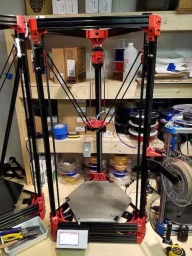
  1. Martin Bogomolni

    Builder

    Joined:
    Sep 23, 2016
    Messages:
    49
    Likes Received:
    3
    Martin Bogomolni published a new build:

    Read more about this build...
     
  2. James_Hopkins

    Builder

    Joined:
    Jul 16, 2015
    Messages:
    28
    Likes Received:
    6
    Can you post some pictures of whats different about yours?
    I have already started printing the Delta-Six vertex pices but i think im using yours. They are the double bottom vertex and single top.
    The double vertex has Z lines that i fixed in my printer as you can see they are not in the single vertex i printed after the double.

    IMG_2736.JPG IMG_2735.JPG IMG_2734.JPG
     

    Attached Files:

  3. Martin Bogomolni

    Builder

    Joined:
    Sep 23, 2016
    Messages:
    49
    Likes Received:
    3
    Jerry's take on the Delta-6 didn't have a separate build thread. Since I'm building one, figured I should start a new thread to keep this particular buildlog well organized.

    At this point, I've printed 3 large vertexes, 3 small vertexes, 3 carriages for big-V-wheels, 3 carriage arm mounts, 3 belt tensioners and the spool holder.

    I still have to print the bowden extruder + effector ( or figure out how to make a direct-drive extruder that fits this design on the effector )

    ----

    I'm also going to be using a different control system than Jerry did. Since I already have the hardware from the WolfStock printer, I'm going to use a Ramps 1.4 board + Marlin w/ Graphical LCD.
     
  4. Martin Bogomolni

    Builder

    Joined:
    Sep 23, 2016
    Messages:
    49
    Likes Received:
    3
    Productive weekend so far! I have dry-assembled the carriages onto the rails, and tested the fit of the vertexes. I've got a @#%-ton of bolts & nuts coming via Amazon on Monday, and I had to buy three more pieces of 20x40 500mm rail from OpenBuilds to finish the sides of the towers.

    I need to figure out the 'ideal' length for the arms once I have the effector printed. My bot is using 500mm sides, and the effector that Jerry designed w/ Traxxas ends. I'll be using a 300mm borosilicate glass bed, with the SeeMeeCNC heated build platform underneath it and bonded with the same 3M product LulzBot uses to join their heater to the glass for best thermal conductivity. I may add a PEI sheet on top, as I've had very good results on the LulzBot TAZ 6 w/ PEI.

    IMG_20161001_110920.jpg
     
  5. Martin Bogomolni

    Builder

    Joined:
    Sep 23, 2016
    Messages:
    49
    Likes Received:
    3
    Hey James,

    What is the cause of the banding on your tall vertex print? It looks like it's happening every 5mm or so in the Z axis?

    -Martin

     
  6. Martin Bogomolni

    Builder

    Joined:
    Sep 23, 2016
    Messages:
    49
    Likes Received:
    3
    More progress! All the carriages are mounted, idlers are mounted, and all the parts for the vertexes are finished. All major components have been printed, and I am just waiting on Amazon to deliver the hardware needed to bolt it all together and OpenBuilds to deliver the cross-pieces I need.

    Servos are ready to go, and I even got some of those nice "quiet" mounts for them. RAMPS 1.4 board and LCD are also programmed and ready to go. 24V power supply is ready, e3d v6 w/ 24V cartridge is ready.

    Now, all I need is to choose an auto-leveling system for this build.

    IMG_20161001_222638.jpg
     
  7. James_Hopkins

    Builder

    Joined:
    Jul 16, 2015
    Messages:
    28
    Likes Received:
    6
    Im not sure what was causing the banding but i think maybe the 8mm threaded rod was bent or something to do with the aluminum coupling between that and the stepper motor. But now its all gone since i replaced it and added a reduction pully.
     
  8. James_Hopkins

    Builder

    Joined:
    Jul 16, 2015
    Messages:
    28
    Likes Received:
    6
    Wow its looking great. Can you post a build list? Like how many of what file i have to print and a list of hardware?
    It would help a lot. I'm kind of guessing right now.

    Also what are your thoughts on using magnets on the rod ends instead of the part used on rc cars?
     
  9. Martin Bogomolni

    Builder

    Joined:
    Sep 23, 2016
    Messages:
    49
    Likes Received:
    3
    Heh, I'm learning as I go along as well.

    So far, it's been:
    I'm sure I've forgotten a few things ... I'll keep track and post as I go along.
     
    #9 Martin Bogomolni, Oct 2, 2016
    Last edited: Oct 3, 2016
  10. Martin Bogomolni

    Builder

    Joined:
    Sep 23, 2016
    Messages:
    49
    Likes Received:
    3
    I have used delta printers that have mag-carriages, and having the carriage fall off during a fast move is a major pain in the *** that can ruin prints. I don't like magnetic effectors for that reason, even though they do offer some advantages in smooth motion.

    A well adjusted traxxas effector works beautifully.
     
  11. Martin Bogomolni

    Builder

    Joined:
    Sep 23, 2016
    Messages:
    49
    Likes Received:
    3
    OH! I also have the carriages mounted upside-down in the photos! I just wanted to slap them on to take the picture ... FLAT END UP --> flat side should be hitting the limit switches.
     
  12. Martin Bogomolni

    Builder

    Joined:
    Sep 23, 2016
    Messages:
    49
    Likes Received:
    3
    More bolt, screws, and the limit switches arrived today. I have installed the limit switches ... still waiting for my OpenBeam extrusions to arrive so I can assemble the base and top.

    Next, I need to make TRAXXAS adapters to go from my 8mm carbon fiber rods to the Traxxas ends w/ epoxy. I've sketched something up in Adobe 123D Design ( just a cylinder that's 10mm in dia, with an 8mm hole in one side, and a 7mm hole on the other side meeting in the middle Nothing fancy )

    I also need to identify the bearings Jerry used on his bowden stepper extruder setup. They are very small ( 3mm ID, and about 10mm OD ) .. I could probably just machine some brass bushings to do the same job.
     
  13. Martin Bogomolni

    Builder

    Joined:
    Sep 23, 2016
    Messages:
    49
    Likes Received:
    3
    Bowden drive extruder is finished (except for the MK8 drive gear) and the limit switches are mounted.

    As it turns out, the required bearings ( 3 of them ) are all 623 bearings, which I had a tube of VXB bearings just "laying around" from a different project ... adding a low-rider stage to my old Cupcake 3D printer.

    IMG_20161003_163616.jpg IMG_20161003_163626.jpg
     
  14. Martin Bogomolni

    Builder

    Joined:
    Sep 23, 2016
    Messages:
    49
    Likes Received:
    3
    I can already tell that mounting the Astrosyn vibration-isolated steppers onto the lower vertexes is going to be a major pain in the arse.
     
  15. James_Hopkins

    Builder

    Joined:
    Jul 16, 2015
    Messages:
    28
    Likes Received:
    6
    Hey It looks like you used the carriage-v3 for large wheels not the one for small wheels? Why did you do that?
     
  16. Martin Bogomolni

    Builder

    Joined:
    Sep 23, 2016
    Messages:
    49
    Likes Received:
    3
    To save money. My build started with a WolfStock delta printer I built a couple years ago ... it has 95% of all the components I needed for this build, and so I had a set of OB large V-Wheels already mounted w/ eccentric spacers on the old carriage assemblies.

    I'm recycling everything I can -- from the 20x40 rails and t-nuts to the RAMPS and steppers. My major expense for this build will be the new 24V power supply, the e3d v6 head, and the new display I got.
     
  17. Martin Bogomolni

    Builder

    Joined:
    Sep 23, 2016
    Messages:
    49
    Likes Received:
    3
  18. Martin Bogomolni

    Builder

    Joined:
    Sep 23, 2016
    Messages:
    49
    Likes Received:
    3
    Yay! The weekend is back again.

    I bought some lengths of 20x40 500mm V-slot OpenBeam from OpenBuilds, and now I need to cut them to exactly 500mm. They send a batch of three that were -just- shy of 500 ( 496-ish ) and they replaced them ... for free .. and OVERNIGHTED the replacements to me.

    The replacements are 500.001 mm. Yes, I measured with a caliper. Great job OpenBuilds!

    So .. six more to go, and time to assemble the frame. Exciting!

    In the meantime, I'll be printing the rod ends and getting ready to do the lay-up and epoxying of all six of 'em on a jig mounted on a 1000mm piece of spare v-slot I have.
     
  19. Martin Bogomolni

    Builder

    Joined:
    Sep 23, 2016
    Messages:
    49
    Likes Received:
    3
    Extruder is mounted into the effector, and the DC42 leveling hardware has been installed!

    IMG_20161008_142559.jpg IMG_20161008_142529.jpg IMG_20161008_142509.jpg
     
  20. Martin Bogomolni

    Builder

    Joined:
    Sep 23, 2016
    Messages:
    49
    Likes Received:
    3
    Sunday progress ... it's a beautiful day, and I've got all the windows of the house open as I build the delta bot in the kitchen.

    So, I need to amend the parts list. When printed, 10mm bolts are just slightly too short to reach the T-nuts so I bought another 50 M5 x 12mm Socket Hex Cap Bolts. This build needs a LOT of these.

    I also found that the M5 bolts I bought to secure the vertexes on the ends are also a shade too short ... so I'll need to remeasure and order new ones. I'll amend the BOM once I know what length is correct.

    Time for pretty pictures:

    The kitchen table in "workbench" mode ... as my six year old daughter builds her own things out of Zoobs. Because, of course, she has to do what we do. *grin*

    IMG_20161009_123600.jpg

    The bot frame with the bottom vertexes connected:

    ( yes, those are Legos in the background ... like parents, like kiddo. )

    IMG_20161009_123541.jpg
     
  21. Martin Bogomolni

    Builder

    Joined:
    Sep 23, 2016
    Messages:
    49
    Likes Received:
    3
    Spent Tuesday night and a bit of this afternoon gluing up the carbon fiber rods. I 3D printed the fixture holders on the TAZ 6, then bolted them to some of the frame components that were cut just 1mm shy of perfect. The rods for this delta printer are 431.8 mm ( 17 inches ) long ... it's a BIG printer, and I also wanted a good balance of rod length to build size. The double-height towers at the bottom lend a lot of stiffness ... but they also steal a lot of build height.

    I used 5-minute gorilla epoxy glue... it's not the best. Next time, I will switch to DuPont 5 minute epoxy or LocTite 5 minute quick-set.

    My rods are 8mm, and I created a rod-end connector for my traxxas joints. I've included the STL here for anyone that might need it. 8mm rods don't flex much, so I'm hoping I won't need to put springs or rubber bands between them.

    IMG_20161011_190123.jpg
    IMG_20161011_185954.jpg
     

    Attached Files:

  22. Martin Bogomolni

    Builder

    Joined:
    Sep 23, 2016
    Messages:
    49
    Likes Received:
    3
    Getting to the final push building the 3D Delta Printer!

    I finished epoxying the delta arms today, and installed them into the printer. Putting the GT2 belts in was ... a royal pain in the tuchus. Even with a really well designed tightening mechanism, it was fiddly work.

    Now, I just have to wait for my amazon order of post-assembly insertable T-Nuts to arrive, and install the extruder assembly and the filament reel holder. Then comes the complex dance of installing the power supply, wiring, RAMPS board, and control LCD panel. Finally, cutting and installing a few small pieces of OpenBeam to hold the build surface.

    So, a good week of workdays, and I'm done!

    It feels REALLY FRIGGING GOOD to build a machine from scratch.
    IMG_20161012_204954.jpg IMG_20161012_204913.jpg IMG_20161012_204846.jpg IMG_20161012_204821.jpg
     
  23. Martin Bogomolni

    Builder

    Joined:
    Sep 23, 2016
    Messages:
    49
    Likes Received:
    3
    Okay, okay ... after looking at the rest of the issue trying to run at 24V on a RAMPS board would cause me ... I've switched. I went over to filastruder.com and purchased one of those new Duet WiFi boards, and a display... not cheap, but definitely The Right Thing(tm) to buy now.

    Filament holder is mounted, extruder is mounted ( I need to find an appropriate tension spring ... might have to go dig at Home Depot ), endstops and steppers are in, bowden tube is in.

    More pictures! Everything is now mounted and bolted in, only the electronics are left to do. The scale of this machine is BIG. I put a tape measure and my old SeeMeeCNC Onyx hotbed ( 320 mm! ) to show you the size of this build.

    If I want to make taller objects ( right now, max height is about 12" ) all I need to do is get some 1500mm extrusions and use them for the verticals. However, being able to make things that are about 12" in diameter and 12" tall really pushes the envelope of most of the things I print with a 0.4mm head.

    IMG_20161014_174255.jpg IMG_20161014_174349.jpg
     
    #23 Martin Bogomolni, Oct 14, 2016
    Last edited: Oct 14, 2016
  24. Martin Bogomolni

    Builder

    Joined:
    Sep 23, 2016
    Messages:
    49
    Likes Received:
    3
    Hot bed mounts! I went ahead and designed some mounts in TinkerCad ( yeah, yeah .. use the tools you know... I'm learning Autocad 123D Design but it's a pain in the *** to use ). STL's are attached.
     

    Attached Files:

    #24 Martin Bogomolni, Oct 15, 2016
    Last edited: Oct 15, 2016
  25. Martin Bogomolni

    Builder

    Joined:
    Sep 23, 2016
    Messages:
    49
    Likes Received:
    3
    I made the slots for M5, but my heated build plate holes and thermal insulation holes are M3 ... D'Oh! Still will work.
     
  26. Martin Bogomolni

    Builder

    Joined:
    Sep 23, 2016
    Messages:
    49
    Likes Received:
    3
    Today is filled with a long, boring print of 5mm side panels. I've decided to go with gray, with just 3 layers top and bottom, and hexagon infill at 15% to give them a honeycomb panel look, slightly translucent. I hope this will let me see some of Das BlinkenLights underneath when the printer is running. If I don't like the look, I can always switch them out for acrylic panels.

    Unfortunately, I don't have a CNC big enough to mill the bottom and top plates. I'll have to go to the hackerspace or TechShop to finish milling those two plates. I definitely need an MDF bottom plate, to hold the electronics.

    The Plan(tm) is to get a 1 Ohm power resistor, and bolt it directly to one of the makerslide pieces as a passive heatsink. Then I'll connect it in series with the Onyx heatbed and run the heatbed at 2.2 Ohms, 24V. The power resistor will get hot, but this will limit the current and let me run the heated bed at ~ 10A / 260W, which will also let me run the whole printer from a 24V 400W power supply.

    So, if everything works out -- I'll use

    I still need to figure out what kind of connectors I want to use for the hotend and other electronic cabling. I'll probably end up using some kind of locking Molex connector for the hotend assembly. Right now, I'm evaluating a number of different wire-to-wire connectors. The one that LulzBot used is nearly impossible to get, so I'm continuing to look for a connector that can take 2 power wires, 3 pairs of fan wires, 2 thermistor wires, and 3 pins for the dc42 prox sensor. If I could find a lightweight, locking, 10 or 12 pin connector that would be perfect.
     
  27. Martin Bogomolni

    Builder

    Joined:
    Sep 23, 2016
    Messages:
    49
    Likes Received:
    3
    Picture! Side panels printed and installed. Looks pretty good. I think I may make some for the top at some point just to match.

    IMG_20161016_180059.jpg
     

    Attached Files:

  28. Ken Bailey

    Builder

    Joined:
    Jan 3, 2017
    Messages:
    2
    Likes Received:
    0
    Martin,
    Have ya printed with it yet ?

    I'm building this monster !

    Ken
     
  29. Martin Bogomolni

    Builder

    Joined:
    Sep 23, 2016
    Messages:
    49
    Likes Received:
    3
    Almost!

    I am still waiting ( believe it or not! ) for my Duet Wifi to come in. Once that's in place, I will be able to print. Everything else has been put together, and ready to rock.

    -M
     
  30. Ken Bailey

    Builder

    Joined:
    Jan 3, 2017
    Messages:
    2
    Likes Received:
    0
    I looked into a direct drive extruder mounted to the hot head. This would work IF you planned on running the bot at slooooow speeds (weight and pendulum effects at higher speed). Look's like from some research that suspending it between the carriages is the best solution for speed and maintaining accurate flow to the hot head. This is the way I will be resolving that issue.

    Ken
     

Share This Page

  1. This site uses cookies to help personalise content, tailor your experience and to keep you logged in if you register.
    By continuing to use this site, you are consenting to our use of cookies.
    Dismiss Notice