Welcome to Our Community

Some features disabled for guests. Register Today.

Dream to practical

Discussion in 'CNC Mills/Routers' started by Bob K, Jul 17, 2016.
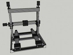
  1. EvanBruner

    EvanBruner Well-Known
    Builder

    Joined:
    Mar 26, 2016
    Messages:
    68
    Likes Received:
    66
    I just mill a pocket into my spoilboard with the corners milled out. Then you can place your piece against the walls of the pocket and you're square the the gantry and should be within a few thou as far as height variation goes. Best way to indicate a corner on wood is to use a conductive touch plate. Next best is to turn the router on and move in one thou increments until you hear a change in the sound or see the bit cutting. You can do the same with manual turning but i found it to be less repeatable. The paper method can be used to zero the bit in the z axis without cutting into the workpiece.

    I would look into getting a 3 axis touch plate. You can make one yourself or buy a very nice piece from here:
    3 Axis Automatic Zero for X-Carve
     
    GrayUK likes this.
  2. Bob K

    Bob K New
    Builder

    Joined:
    Jun 2, 2016
    Messages:
    55
    Likes Received:
    20
    Justin - I think I'm probably making too big a deal on the zeroing of a work piece. I did a small test cut yesterday and setting it up the way you mentioned was OK.

    Thanks

    Bob
     
  3. Bob K

    Bob K New
    Builder

    Joined:
    Jun 2, 2016
    Messages:
    55
    Likes Received:
    20
    Can anyone point me to a method/program to convert G02/G03 commands from Radius format to I J format?

    I got a surprise on yesterday's cut. I found out that Marlin doesn't like the G02/G03 commands in the Radius format. SketchUcam sometimes uses the Radius form and sometimes uses the I J format.

    As best I can tell there's not an option/switch to tell SketchUcam to use only one format or the other.

    I've been looking for a free method of converting the Radius format to I J but haven't struck gold.

    I already use an Excel macro to massage the SketchUcam output to suit Marlin so I'm working on adding the Radius conversion to it.

    Bob
     
  4. Bob K

    Bob K New
    Builder

    Joined:
    Jun 2, 2016
    Messages:
    55
    Likes Received:
    20
    The bleeding edge of Marlin now has radius format support for the G2/G3 commands, has G38.2 & G38.3 commands and will soon have M3, M4 & M5 commands (for us SuperPID users).

    I've just installed hall effect limit switches on my machine. I was able to put them inside the slots on the rails so they're almost invisible. I glued cylindrical super magnets into existing holes in the gantry plate so they also are hard to spot.

    How do people usually set/position the limit switches? Seems to me it's a painful process. I ended up playing with the firmware to toggle an LED on the controller whenever an end stop changed state.

    As long as I'm playing with the firmware ... I could propose a new command or operating mode to make positioning the limit switches easier. Any suggestions as to how the new command/mode should behave?

    I'm thinking that toggling an LED whenever an end stop changes state and printing which end stop it was. You'd also be able to move the X, Y and Z axis in this mode. I'm envisioning the process would be along the lines of:
    1. position the axis where the end stop should activate
    2. start the new command
    3. move the end stop until the LED changes state (probably do this a couple of times)
    4. secure the end stop in place
    5. move the axis to verify the end stop is correctly placed
    6. repeat for each end stop
     

Share This Page

  1. This site uses cookies to help personalise content, tailor your experience and to keep you logged in if you register.
    By continuing to use this site, you are consenting to our use of cookies.
    Dismiss Notice