That arrangement would also further reduce belt length which would be a plus w.r.t. potential stretching effects from the weight of your Z plate assembly. However, unless you implement it as a rack and pinion linear belt (belt-on-belt drive or tractor) you will still likely issues with belt stretching unless you employ some constant force offset springs to, in effect, make your Z axis weightless. However, in the arrangement you have above, you only need to use a belt to drive your lower rod shaft. If you used cables instead of belts for the actual bed it would eliminate any stretching problem - you would just need to find type of pulley with enough traction to drive a cable or find a suitable roller chain/sprocket.
The plan is to drive only the lower rod with 20T GT2 pulleys and a short closed loop belt. Rostocks use a non stretch woven fishing line and winding pulleys, so I may try something similar.
I have a friend that designed large format (12" x 24" or bigger, can't remember) 3D printer with counter weights for his Z-axis. Haven't seen one here though... Seems like a set of constant force springs would be more compact/less complex to implement and able to more evenly distribute the force though. Not doing that on my build though - gravity effects on my 400mm x 400mm Z axis actually assist in further reduction of potential backlash and gantry movement acceleration/deceleration effects (my gantry moves on Z - build plate/bed is fixed). I like Giuliano's belt drive idea though - though I don't anticipate it, if I encounter any unacceptable Z banding issues, a similar belt setup would be worth a look.
Now those would do the trick quite nicely! A Rostock-like setup would probably be ok (and definitely cheaper) - but I believe the performance of those belts would be superior. And with minimal torque losses, you could actually drive both sides with a single stepper via another (steel reinforced) belt if desired. Looks like you'd need to find a different supplier though (or just go the Rostock route).
Not cheap, though - the PosiDrive open-ended belt starts out at around $9.77 per foot for either the Aramid Fiber or Stainless Steel cores: http://sdp-si.com/eStore/Catalog/PartNumber/S7913Y-20AF http://sdp-si.com/eStore/Catalog/PartNumber/S7913Y-20SS And the pulleys.. they're about $20 each. Not to mention, they're all specified in imperial measurements instead of metric - that can't be good for layer heights when everything else is metric. Here's what I have so far, based on 6mm wide GT2 belt, 8mm drill rod, 20T pulleys, and bog-standard 608 bearings. Lower rod is driven by closed-loop belt to the stepper (it's a heavy duty one), and the blue belts raise/lower the Z rail. Although I do like the idea of the constant-force springs - one at each end of the Z rail would offset the weight, making the belts only have to pull the rail down instead of holding it up.
I like it! Properly balanced, constant force springs would also reduce Z axis drop forces in the event of loss of power to the steppers. In fact it may still allow the bed to be suspended in absence of power to the steppers. Regardless it would certainly prevent the build plate from slamming to the bottom during such an event. Depending on your pulley selection and stepping resolution, you should be able to obtain ~10 micron resolution with this setup as well. I think this is the max my lead screws can do so I don't think you aren't giving up anything going this route - just adding a slight amount of cost/complexity but not too much. Looking forward to seeing it's performance!
1.8 degree stepper with 1/16 stepping, and a 16 tooth pulley would get me 10 micron. If I put a 32T pulley on the 8mm driving shaft, and a 16T pulley on the stepper motor, I could theoretically get a 5 micron capability. It would also let me do 1/8 stepping for 10 micron, for more accurate steps and holding power.
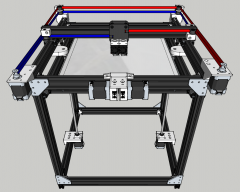
I think I'll go forward with the GT2 belt arrangement - as nice as the PosiDrive system is, it's not metric. Belt-driven 16T/32T will give a nice 2:1 reduction, and an even amount of steps for 10 micron. Here's the view from the inside of the frame, with the driving belt (red) and the vertical motion belt (blue). The red belt will be a GT2 6mm wide closed loop belt, 122-124 teeth long. Conveniently, RobotDigg has them for cheap: http://www.robotdigg.com/product/203/122mm,-124mm-OR-132mm-long-2GT-6-endless-belt The blue belt will just be an open length of GT2 belt. I'll probably work in some kind of belt tensioner system for the blue belts as well. The stepper motor mount will be just a piece of 2" 6063 aluminum angle - I'll have to cut and drill, but that shouldn't be difficult.
I did some expected weight calculations - I weighed a 500mm piece of 20x40, and it came out to be just about 0.75 grams per linear millimeter. So I took the measurements of the four bars that would form the main frame of the Z-plate, and they totaled about 4 pounds. If I add on a 1/4" thick, 16x20" MIC6 cast aluminum plate on top of that as a heat spreader, it adds another 8 pounds. So, I would have to counterbalance for a pretty heavy 12 pounds or so, for a distance of about 24" or so. I think these 2.63 pound springs would do, if I had four of them: Stainless Steel Constant-Force Spring, 4000 Cycle Life, .008" Thick, 30.0" Long, .5" Wide: #9293K52 They wouldn't offset all of the weight, but it would take a good 10 pounds or so off. I'm thinking I could mount them on top of the frame, on ball bearings.
Are you sure? They're tight wound, so they have to rotate as the free end gets pulled out. The spring force comes from that rotation, or so I read... A pair of S696ZZ (6x15x5) should fit the ID of the spring coil.
You already have a horizontal rod available for your upper pulleys - 8mm right? You could use 8x15x24 linear bearings ($0.80 from robodigg) - or for this application even a self lubricating bronze bearing ($0.60) would work. And if it were me I would probably go with the 9293K54 spring (same price but 4.12 lb.) for a total of 16.48 lbs force. When you add screws and other hardware, heating element, glass or Ultem be plate, etc., you are likely to be closer to 16 lbs. Also, a net positive force may not be a bad thing (the less total force you have in either direction will reduce potential belt stretching issues).
I like that idea - the larger springs have an inner diameter of about .73" / 18.5mm, so I would have to find a bearing with an ID of 8mm and an OD of 18mm. Or just use those bronze bearings (8mm ID, 12mm OD) and print a sleeve to make up the difference.
How about a video? That is a different kind of spring - a loose-wound spring that is tightened when the tape spool is pulled, and retracts back to its loose-wound state. Those kinds of springs are rotation based with an anchor in the center - otherwise the spring inside the drum has nothing to tighten against. These constant force springs are tight-wound, and have to be free-wheeling in the center so they can rotate - the spring tension is made when the spring is pulled out. You can see some better pictures and diagrams at SDP-SI: https://sdp-si.com/eStore/Catalog/Group/65
Upper rod assembly with bronze bearing (orange), plastic printed insert (green), and constant-force spring: Full assembly:
There are also these @ 3.5lbs. each: http://www.amazon.com/dp/B0085ZXEDW/ref=biss_dp_t_asn They are a little larger but are only $12.67 shipped for 5 of them...
During one print cycle, the average printer cycles up and down the Z axis twice. Once for homing/calibration and once for the actual print. So if you printed one object a day 365 days a year it would take you 5 1/2 years to cycle 4000 times. In addition, the (minimum guaranteed) cycle life is for the guaranteed load tolerance of the spring. It doesn't mean the spring will stop working after 4000 cycles. And since the use case is for a load offset (not necessarily for perfect balance) all it means is that, using the springs from Amazon noted above, if four of them offset 14 lbs when new, after say 6-8000 cycles they may only offset 11-12. Since the load is distributed amongst 4 belts than each belt may be in tension by a half lb. or so - still completely usable and unlikely to cause stretching issues but if you are worried about it you can spend $13 and replace the springs every 5 years...
Yeah, what Tom said. It would be a little different if the springs were compensating against a load that moved quickly and often - such as on Delta rails that go up and down all the time... You'd end up going through 4000 cycles in a short amount of time. But not with something like this - the springs are there to compensate for a mostly static load, that moves slowly in either direction.
I think I will go with these - 3.5 pounds adds up to 14 pounds of lift if I use 4, and it leaves me with a spare.
Front view of the assembly, with the setup mirrored on the back side of the frame. I'll probably have to design some kind of a printed part to support the bearing in the center of the lower rods, next to the red belt. The red belt will need to be tensioned, and the rod needs a support to resist the tensioning force. With the vertical V-Slot beams lengthened to 600mm, there's just over 430mm of vertical build space.
I suspect that for greatest longevity it would be best for the plate the be left at the top (almost fully coiled springs) - not something it will default to unpowered without mechanical assistance unless your net force is positive (which if you did design it for, would also provide an intrinsic indication of weakened springs).
Vertical movement of your lower rod will provide tensioning adjustment for your red belt. And if you move your Z stepper and drive pulley closer to one end you would likely not need additional shaft support.
I managed to find a piece of .040" (1mm) thick PEI for a print surface, 24" x 24" for about $52: http://www.zoro.com/i/G2846611/ It'll go on top of the 1/4" aluminum heat bed, attached with wide strips of adhesive tape.
Seems kind of pricey for that thin of a piece! And I would be afraid of trying to mount that thin of a piece of material semi-permanently to my build plate/heat spreader. I've seen some decent results from a simple acrylic sheet (which also isn't cheap but certaily is compared to ultem) using lower bed temps. https://lesagegp.wordpress.com/2013/10/06/acrylic-sheet-for-print-surface/ I think I am going to try acrylic first. I plan on buying a large sheet to enclose my printer anyway so I will have plenty left over - and since it is thicker I can probably sand and reuse as needed. And if it doesn't perform well enough I will probably get this: http://www.ebay.com/itm/25-x-16-x-1...158?pt=LH_DefaultDomain_0&hash=item3a9577fa16 More than twice as much as the zoro option but imminently resurface-able through light sanding and less likely to damage (I saw a picture of am ultem sheet someone was using that cracked - suspicion was difference in thermal expansion of aluminum plate vs. the ultem - this would also be a concern if you are planning to glue it to your heat spreader).
Trust me, if I were to get a 20"x16" piece that's 1/4" thick, it would be at least $150. The .040 thickness is thin at 1mm, but its what others have recommended. It will be taped to the aluminum with special 3M tape - I figure applying it with a roll of 4-5" tape in strips will be fine. See the PEI link above - people have been testing PEI as recently as February 2015.
I didn't realize you were increasing your build area to 20"x16" - I haven't seen any decent prices for anything over 16"x16". I have read that link before, as well as many others with mixed results so I'm not ready to jump just yet. And if I do, I plan on using a thick enough piece to be removable so I can use different print surfaces (e.g. bakelite for nylon, ultem for general printing, glass for some prints, etc.). Though I suppose I could tape a thin sheet of ultem to glass and have a reversible plate and just switch to the bakelite sheet when I want to print nylon...
I modeled the hot end based on the E3D Cyclops, but I think ill go with dual Volcano nozzles in the same heat sink. With a 0.4mm nozzle for detail, and maybe a 0.8 or 1mm nozzle for infill. As it is I wont be able to go beyond 2 extruders anyways, until an expansion board is made for the CRAMPS board.