Welcome to Our Community

Some features disabled for guests. Register Today.

Hurricane - Large 800mm³ build space project

Discussion in '3D printers' started by lenne0815, Dec 20, 2015.
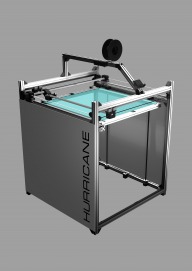
  1. lenne0815

    lenne0815 New
    Builder

    Joined:
    Dec 20, 2015
    Messages:
    22
    Likes Received:
    14
    #1 lenne0815, Dec 20, 2015
    Last edited: Dec 20, 2015
  2. lenne0815

    lenne0815 New
    Builder

    Joined:
    Dec 20, 2015
    Messages:
    22
    Likes Received:
    14
    Today i ordered all the parts i need for building the printer with a single extruder, so christmas already starts of very well ;)
    For the side panels i chosed HPL compact board, which is rather cheap in comparison to other plastics but very rigid structurally.
     
  3. lenne0815

    lenne0815 New
    Builder

    Joined:
    Dec 20, 2015
    Messages:
    22
    Likes Received:
    14
    So after the extrusions finally arrived i just quickly assembled them to get an basic idea of the size:

    20160107_193548.jpg

    Didnt expect it to be that huge, especially not after roughly checking everything with an carpententers rule :D

    But in the end the cheapest thing on this printer is the size at just 7,30€ a meter for the aluminium extrusions.

    20160107_193606.jpg

    El cheapo sainsmart Ramps 1.4, flashing with marlin and setting up the basics to test the steppers was a breeze ( I propably switch the Ramps later on with something better )

    20160107_193743.jpg

    And here it gets interesting finally, maybe someone guesses what these blocks are all about and what differenciates this printer from anything ive seen so far ;)

    20160107_193826.jpg
    Another closeup where u can see the two smaller bearings inside 2 of 3 block parts which are used to press the belt onto the pulleys.

    For finishing the X/Y assembly i gonna need 4 blocks but only two steppers.
     
    #3 lenne0815, Jan 7, 2016
    Last edited: Jan 7, 2016
    MaryD and Mark Carew like this.
  4. Keteland

    Keteland New
    Builder

    Joined:
    Dec 18, 2014
    Messages:
    16
    Likes Received:
    7
    Hello Ienne0815 !
    Wahooo ! Big build ! Big challenge as well, I guess !

    About the structure : will you use your side panels for the bracing of the structure ? You will probably need cross bracing anyway, to avoid deformations of the cube ("carpenting consideration"), as your panels may be too large to keep perfectly straight, even if they are well attached on the structure (or they are thick enough to be strong).

    About the electronics : I just published today a large 3D printer (but not as big as yours …), based on Mytechno3d's Maximus 3D printer. I also used a Ramps 1.4 and a Freaduino Mega 2560.
    After connecting everything, I got a weird problem : I can activate extruder, ventilators, heating bed … but not the motors (they do not move at all !). Even after several verifications of the connections, tension …etc. I chose NEMA 23 (big motors, probably what you may need for your build). It's very frustrating !

    So, I am interested by the way you will build the electronic parts (Ramps 1.4, Arduino plates …etc), and eventually, by the "computing details" : firmware, Marlin, …etc.


    Bon courage et à bientôt !
     
    lenne0815 likes this.
  5. lenne0815

    lenne0815 New
    Builder

    Joined:
    Dec 20, 2015
    Messages:
    22
    Likes Received:
    14
    Cheers ! Yes, the panels act as cross braces. Im really trying to get away with nema 17 steppers and i do hope that the drylin bearings ( and the way im using them ) will make that happen. I have quite some experience with stepper tuning ( i build several big gantry style routers already ) so i think ill get it moving atleast, what tradeoffs i have to make with accel rates / top speed is another thing ;) ( i actually would have a way out if the machine ends up to slow, i can just double up the steppers on x/y and use slaved external drivers for them )

    I dont know if i can be of any help with the non moving steppers though, do you supply enough voltage to the stepper drivers ( u need external drivers with nema 23s i suppose ) ? Nema 23s usually run at 48volts, my cnc setups run at 60volts ( with leadshine dm 860 drivers )

    Most of the functions i need later on i already saw when flashing the ramps, so i think its more a matter of finetuning than to reinvent anything
     
    #5 lenne0815, Jan 7, 2016
    Last edited: Jan 7, 2016
  6. Keteland

    Keteland New
    Builder

    Joined:
    Dec 18, 2014
    Messages:
    16
    Likes Received:
    7
    Hello !
    I will check the voltage of my NEMA 23 motors, but I have a 12V power supply … so, it should be logically 12V. I think I understand what you mean by "external driver", but I do not know anything about it (as I said, I 'm a real beginner in the field). I found some videos about leadshine dm 860 drivers (I will watch it tonight).
    Do you know where I could find a kind of "assembly instructions" about that ?
     
  7. lenne0815

    lenne0815 New
    Builder

    Joined:
    Dec 20, 2015
    Messages:
    22
    Likes Received:
    14
    Yeah, i think u are trying to use the stepstick drivers for the nema 23s, that doesnt really work. U can remove the stepsticks and just use the pinouts for the Step +/- and dir +/- and route them into the external drivers. I had a look at your build and i think the nema 23s are way overkill, they are ( Witch a proper driver ) so strong that they can bend / rip apart the whole construction. I would highly advise to just use nema 17s with the stepsticks u have now !

    On another note - i wouldnt insulate the cables like that, with the amps were pushing for the hotend and just one bad solderjoint thats a recipe for disaster ;) Just use proper cable chains, they are so cheap these days on ebay.
     
    #7 lenne0815, Jan 8, 2016
    Last edited: Jan 8, 2016
  8. lenne0815

    lenne0815 New
    Builder

    Joined:
    Dec 20, 2015
    Messages:
    22
    Likes Received:
    14
    Tiny steps in the right direction:

    20160108_121724.jpg

    My assumption that the original E3D Volcano addon fits into the chinese Ripoff base was right.

    The reason i Frankensteined the Hotend should be obvious to anyone who ever saw how a Chinese Nozzle is drilled ;)

    ( on another note, could a moderator pls change the title in the forum ? I just suck at mathmatics ;) )
     
  9. Keteland

    Keteland New
    Builder

    Joined:
    Dec 18, 2014
    Messages:
    16
    Likes Received:
    7
    Thank you for your advise. I'll make it up this WE, and get NEMA 17 to replace the NEMA 23, to see what happens. I 'll tell you if I succeed !

    For the E3D Volcano, I have got one. Good hot end. The nozzles are a bit fragile when you want to replace one to install a bigger/smaller filament (mine are getting "smached" by my wrench …). I'll replace them by stainless steel nozzles, or hardened steel nozzles.

    For Frankensteining the rest : "why not ?"
     
  10. lenne0815

    lenne0815 New
    Builder

    Joined:
    Dec 20, 2015
    Messages:
    22
    Likes Received:
    14
    #10 lenne0815, Jan 8, 2016
    Last edited: Jan 8, 2016
  11. lenne0815

    lenne0815 New
    Builder

    Joined:
    Dec 20, 2015
    Messages:
    22
    Likes Received:
    14
    I needed to cut down the supports from my supported Rails in the workshop ( China at its finest, 1001mm instead on 1000 ;) rails seem fine though ) so i took some pics of one of my monsters

    20160108_171625.jpg 20160108_171647.jpg 20160108_171657.jpg

    This machine runs on nema 23s with leadshine dm856 drivers, just to get an idea what power to expect out of nema 23s, on x it has so much force it would propably break my arm if i go in its way. Wiring etc is completely foobared but it runs reliably every day.
    It has all the yadda yadda of expensive machines like THK linear bearings and ISEL ballscrews / bearings.
    It even has custom made driven ballbearings for the gantry ballscrews i havent seen anyone ever use in a diy build.

    Back to the Printer i cut some threads for the feet:

    20160108_203445.jpg

    I hate cutting threads.
     
    #11 lenne0815, Jan 8, 2016
    Last edited: Jan 8, 2016
  12. lenne0815

    lenne0815 New
    Builder

    Joined:
    Dec 20, 2015
    Messages:
    22
    Likes Received:
    14
    I printed some small blocks with two bearings which will later hold the trapezoidal spindle which in turn moves the bed assembly:

    20160109_191908.jpg

    All in all i gonna need eight of these but at 1 1/2 hrs per print thex are pretty fast to do.

    20160109_192815.jpg
     
  13. lenne0815

    lenne0815 New
    Builder

    Joined:
    Dec 20, 2015
    Messages:
    22
    Likes Received:
    14
    Redrew and printed the holders for the brass trapezoidal nuts.

    20160110_150400.jpg
    20160110_150408.jpg

    Almost done !

    20160110_235203_Richtone(HDR).jpg
     
  14. lenne0815

    lenne0815 New
    Builder

    Joined:
    Dec 20, 2015
    Messages:
    22
    Likes Received:
    14
    A little update here:

    First i drilled all the holes for mounting the linear guides and then mounted them by simply screwing all the way through the support right into the linear guide. I tried mounting them to Profiles the "normal" way before, but even when drilling the profiles with a bench drill the bit runs away and creates really ugly / imprecise holes.

    20160113_133140_Richtone(HDR).jpg
    20160113_133158_Richtone(HDR).jpg
    After receiving the Drylin nuts i realised that they are not pretensioned and need some kind of clamping mechanism to squish them to the rails.
    So i redesigned the Cross section / Hotend holder and printed it:

    20160113_133004_Richtone(HDR).jpg

    Thats it for now, i might even get the first axis to move tonight so i could roughly work out what accel rates / speed i can drive the assembly at.
     
  15. lenne0815

    lenne0815 New
    Builder

    Joined:
    Dec 20, 2015
    Messages:
    22
    Likes Received:
    14
    Getting X / Y to work will take a little longer because i needed to refine some of my drawings after realising that bearings with 24mm outer diameter dont press the belt tightly enough onto the stepper pulley.

    So i went ahead and started the bed assembly.

    Made some Brackets to mount the base frame:

    20160124_113019.jpg

    Mounted my trapezoidal spindle holders, drilled the big pulleys to an inner diameter of 12mm and fixed them to the spindle.

    20160124_113042.jpg

    After mounting everything i reduced the amount of friction by carefully adjusting the blocks / nut holders.

    Pic of one side fully assembled

    20160124_113054.jpg

    Pics of the HPL compact board ( 6mm ) which i cut, drilled and beveled for cross bracing / side Panels.

    20160124_113129.jpg

    20160124_113107.jpg
     
  16. David Klug

    Builder

    Joined:
    Jan 21, 2016
    Messages:
    4
    Likes Received:
    0
    Can you explain to me how you made a closed loop out of your z-axis gt2 belt? A normal belt clamp wouldn't work with the belt running over the pulleys right?
     
  17. lenne0815

    lenne0815 New
    Builder

    Joined:
    Dec 20, 2015
    Messages:
    22
    Likes Received:
    14
    Hey david, you can just buy them fortunatly ;) i bought the longest ones i could find at about 800mm to get the rods spaced apart as far as possible.
     
    #17 lenne0815, Jan 25, 2016
    Last edited: Jan 25, 2016
  18. lenne0815

    lenne0815 New
    Builder

    Joined:
    Dec 20, 2015
    Messages:
    22
    Likes Received:
    14
    Ive got the Table assembly up and running today !

    Firmware wise it was really easy once again, Marlin is prepared to slave the second extruder stepper to Z so i just activated that option, afterwards i did a quick calculation to set up steps per unit properly which was easy once again because the small pulley has 20 teeth and the large one 60.

    What was as difficult as expected was to set up the alignment correctly which took the better part of today, these trapezoidal spindles jam extremely easily and need to be set up really carefully.

    I needed to reverse one stepper which i achieved by just rotating the plug. dont ask why ;) .

    20160127_223201.jpg

    20160127_223213.jpg

    20160127_223219.jpg

    20160127_223225.jpg
     
  19. lenne0815

    lenne0815 New
    Builder

    Joined:
    Dec 20, 2015
    Messages:
    22
    Likes Received:
    14
    Got the X axis up and running, from what ive seen so far i might Gzero @ about 3000mm/m which is okayish for now, maybe i can go a bit further with proper alignment and watercooled stepsticks ;)

    20160128_031529.jpg

    20160128_031552.jpg

    20160128_031609.jpg
     
  20. lenne0815

    lenne0815 New
    Builder

    Joined:
    Dec 20, 2015
    Messages:
    22
    Likes Received:
    14
    Goddamit ! Just mounted the Y axis, tested how the axles work together - realised i ordered only 2 meters gt2 belt instead of 4, so no gcode running for me today :(

    Aside from that everything works as expected so far and im sure now that the base concept will work.

    20160128_140104.jpg

    20160128_140122.jpg
     
  21. lenne0815

    lenne0815 New
    Builder

    Joined:
    Dec 20, 2015
    Messages:
    22
    Likes Received:
    14
    It could atleast print standard kitchen cabinets :D

    Just sliced one example model in vase mode, the times arent to bad, this thing Twisted 6-sided Vase Basic by MaakMijnIdee would only take about 30 hours at 800mm height.
     
  22. lenne0815

    lenne0815 New
    Builder

    Joined:
    Dec 20, 2015
    Messages:
    22
    Likes Received:
    14
    While not being able to work on x / y i made the spool holder / Filament drive assembly:

    20160129_124709.jpg


    20160129_124822.jpg
     
  23. lenne0815

    lenne0815 New
    Builder

    Joined:
    Dec 20, 2015
    Messages:
    22
    Likes Received:
    14
    There actually is quite a bit of side support inside

    20160129_203802.jpg

    I cant image the spool ( even completely empty ) just hopping over a 2cm ledge.
     
  24. lenne0815

    lenne0815 New
    Builder

    Joined:
    Dec 20, 2015
    Messages:
    22
    Likes Received:
    14
    G Code up and running

     
  25. andrebj

    andrebj New
    Builder

    Joined:
    Nov 23, 2016
    Messages:
    1
    Likes Received:
    0
    Nice project sir! Thinking make one, could you share the components and the project? thanks!
     
  26. Ozfunghi

    Ozfunghi New
    Builder

    Joined:
    Feb 13, 2017
    Messages:
    2
    Likes Received:
    0
    Any updates? Very interesting project.
     
  27. robb_nl

    robb_nl New
    Builder

    Joined:
    Apr 22, 2017
    Messages:
    3
    Likes Received:
    2
    Can you explain how your X-Y movement works? Why did you choose this instead of (proven) CoreX-Y?

    Nice video! Good to see it is working. Can you show a video of high-speed movement too? Since you have a very large buildvolume, my guess is you want high speeds too, otherwise prints will take eternity to finish.

    I realize this is a WIP, but will you be posting a BOM?
     
    #27 robb_nl, Apr 23, 2017
    Last edited: Apr 23, 2017
  28. Perdurable

    Builder

    Joined:
    Oct 28, 2016
    Messages:
    1
    Likes Received:
    2
    This is the reason I like this build so much. I wish he would continue posting. I believe he used this movement type because it will have less X/Y slop caused by the very longs belts in a Core XY. Or at least in theory!
     
    #28 Perdurable, Jan 20, 2018
    Last edited: Feb 8, 2019
  29. TECNC

    TECNC New
    Builder

    Joined:
    Sep 6, 2018
    Messages:
    1
    Likes Received:
    0
    Any Current update on this?? Extremely wanting to build a Printer like this
     

Share This Page

  1. This site uses cookies to help personalise content, tailor your experience and to keep you logged in if you register.
    By continuing to use this site, you are consenting to our use of cookies.
    Dismiss Notice