Welcome to Our Community

Some features disabled for guests. Register Today.

Inspired by the Crawlbot

Discussion in 'CNC Mills/Routers' started by Craig, Mar 29, 2017.
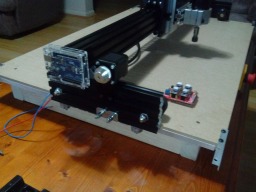
  1. Craig

    Craig New
    Builder

    Joined:
    Feb 27, 2014
    Messages:
    12
    Likes Received:
    22
  2. Kevon Ritter

    Kevon Ritter Veteran
    Builder

    Joined:
    Apr 30, 2015
    Messages:
    597
    Likes Received:
    292
    Or if a fore/aft load is too high, won't it just slip?
     
  3. Craig

    Craig New
    Builder

    Joined:
    Feb 27, 2014
    Messages:
    12
    Likes Received:
    22
    This CNC will have a vacuum system attached like my others. I have never really had a problem with large chips when milling, but its not to say it wont happen! I don't think it will be an issue if the correct tools, speeds and depth cuts are used. I have mainly produced just fine saw dust in my other projects from various timbers, but again i have the vacuum system attached to pick it up. But if it was an issue, I have seen machines set up with weather strip brushes that could run around the wheels to address those sorts of problems. Thanks for the question!
     
    #3 Craig, Mar 29, 2017
    Last edited: Mar 29, 2017
  4. Craig

    Craig New
    Builder

    Joined:
    Feb 27, 2014
    Messages:
    12
    Likes Received:
    22
    When you mean slip, do you mean lift up? Or will it slip in the Y axis ?
    On the Y Axis, there are bearings that run along the edge of the MDF (2 delrin wheels attached under the Y Rail on either side) When I pull the Y Rails (the ones with the skateboard wheels) in tight on opposite edges of the MDF board, it not only glides smoothly along the Y, there is also no twist. (Providing the MDF you are buying from your supplier is perfectly square) But I am only placing these stresses onto the gantry manually at the moment (but quite forceably i might add). The real test will be when the motors are connected and its milling something. You may see in the photos that I have reinforced the edge of the MDF with aluminum angle for the delrin wheels to run on.. I found that when I manually ran the gantry up and down the MDF at first, the delrin wheels started to almost immediately wear into the exposed edge of the MDF (which was expected) which would mean constant re-adjustment as it wore down the edge (a flaw I suspect in the Crawlbot) The aluminium angle is a cheap as well as permanent alternative to this. The GT2 belts will then run from the motor, (there are 2 motors on the Y axis at either end) down to the small bearings and then attached at either end of the board. (More photos to come on this setup soon as the belts arrived today) This is what will run the machine in the Y-Axis
    If you mean the lifting of the Z axis, without a lower wheel or bearing running underneath the board, that I have yet to test. Now the Crawlbot does not have bearings/wheel underneath and rely's on the weight of the unit to keep it down, but of course you would have to be still very weary of cutting depths and speeds, tooling and feeds etc etc. The "Low Rider CNC by Visious" has based his design on the Crawlbot, but introduced adjustable lower wheels to his design, to ensure the Z Axis does not lift. In saying that, if the lifting becomes to much of an issue that I cannot overcome, I have already designed the adjustable bottom wheels to be attached.
    Hope I have answered that for you (or was I off track?)
     
    #4 Craig, Mar 29, 2017
    Last edited: Mar 30, 2017
  5. Tracy Ranson

    Tracy Ranson Well-Known
    Builder

    Joined:
    Nov 4, 2014
    Messages:
    88
    Likes Received:
    32
    Since you are running on the outside rather than the inside, why not go with the wider more industrial HTD belt system or a lead screw?
     
  6. Craig

    Craig New
    Builder

    Joined:
    Feb 27, 2014
    Messages:
    12
    Likes Received:
    22
    On my larger gantry, I will be running a 10mm or even 15mm wide belt on the outside (but haven't quite decided on belt type, pulley size etc as of yet). Currently on my smaller version, 6mm will be fine but have to be sure that the belt is the wired reinforced type. (Test by tightly bending it, it puts a kink in it) otherwise it is only good for 3D printers or similar! I am currently running the same GT2 belt on my other CNC and have not had any problems with stretching, accuracy etc. But again, it is totally up to the user, and what ever people feels works best for them. I can only base my opinions on experience.
    The idea of my larger CNC is so that I could easily pack it away when not in use, so a leadscrew (especially when i make my table over 3 metres long) may be costly and not as portable, as the motors would have to be attached to the table. Again, it is up to the user and the configuration they desire. The great thing about using V-Slot for the Y-Ends, is that you could easily attach a 8mm lead screw nut block to the outside onto the extrusion with a leadscrew running down the outside instead of a belt is defiantly an option for a permant setup, and still be saving money on materials for the Y-Axis track.
     
    #6 Craig, Apr 1, 2017
    Last edited: Apr 1, 2017
  7. Kevon Ritter

    Kevon Ritter Veteran
    Builder

    Joined:
    Apr 30, 2015
    Messages:
    597
    Likes Received:
    292
    I meant, "the wheels are spinning, but the machine is not moving due to excessive cutting load."
     
  8. Rick 2.0

    Rick 2.0 OpenBuilds Team
    Staff Member Moderator Builder Resident Builder

    Joined:
    Dec 20, 2013
    Messages:
    2,852
    Likes Received:
    1,524
    Coming along nicely. :thumbsup: Can't wait to see it come to life...
     
  9. David Bunch

    David Bunch Veteran
    Builder

    Joined:
    Oct 27, 2014
    Messages:
    622
    Likes Received:
    427
  10. Craig

    Craig New
    Builder

    Joined:
    Feb 27, 2014
    Messages:
    12
    Likes Received:
    22
    Kevon
    Will not be any different to any other machine that runs a belt system. The wheels are only a guide, the movement and torque is from the motor and belt. You also have to understand what the machine is capable of depending on the setup and I think the only real way to learn this is from experience (as well as researching as much of the internet of course). Any machine that you apply to much cutting force outside of it capability is going to miss steps. On my other desktop CNC I built (similar to the ShapeOKO machine), I am running 60oz nema17 motors with 500w spindle. For example: Cuts MDF at 1mm depth, about 15mm/sec (The MDF I get is high density) with 2 flute carbide bits. So the only time I have experienced heavy cutting load, is when the CNC is feed rate is too high (or too low), cutting too deep in a single pass, and/or the tool is blunt etc etc. Again, you have to know what the machine is capable of doing with the type of router being used. My first experience with CNC's was about 18 years ago with glass, and man you quickly learn about feed rates on those things.
     
    #10 Craig, Apr 1, 2017
    Last edited: Apr 1, 2017
  11. Craig

    Craig New
    Builder

    Joined:
    Feb 27, 2014
    Messages:
    12
    Likes Received:
    22
    Yes, I made reference to it in an earlier reply. I have been following the project closely and only come across the Crawlbot design, because the Low Rider made reference to it. The Low Rider has introduced bottom adjustable guide wheels (unlike the Crawlbot) possibly because the Low Rider machine would be significantly lighter and the Crawlbot relies on weight to keep the machine down. Like the MPCNC, great design.
     
    #11 Craig, Apr 1, 2017
    Last edited: Apr 2, 2017
  12. matt_o_70

    matt_o_70 New
    Builder

    Joined:
    Dec 15, 2013
    Messages:
    54
    Likes Received:
    15
    Craig - Nice work - I like the Crawlbot concept and can't wait to see how your machine performs.
     
    Craig likes this.
  13. Adam Filipowicz

    Adam Filipowicz Journeyman
    Builder

    Joined:
    Dec 21, 2014
    Messages:
    259
    Likes Received:
    129
    Love the idea of being able to clamp a gantry to a standard sheet of MDF, I would like to build something inspired by these designs but that doesnt need belt on sides, Im thinking of actively powering wheels to move down the sheet
     
  14. Craig

    Craig New
    Builder

    Joined:
    Feb 27, 2014
    Messages:
    12
    Likes Received:
    22
    Hi Adam,

    Unfortunately in my setup, the forces of the router will be too much for just motorized skateboard wheels to rely on movement in the Y-axis during milling. The only thing I can think of is that a rack and pinion may be of an advantage to your idea.
     
  15. Adam Filipowicz

    Adam Filipowicz Journeyman
    Builder

    Joined:
    Dec 21, 2014
    Messages:
    259
    Likes Received:
    129

    Hmm I was thinking of Tank tracks , Above and Below the Cutting Board :D
     
  16. James1949

    James1949 New
    Builder

    Joined:
    Apr 6, 2017
    Messages:
    11
    Likes Received:
    1
    What are you using for spacer between skate wheel and rail?
     
  17. Craig

    Craig New
    Builder

    Joined:
    Feb 27, 2014
    Messages:
    12
    Likes Received:
    22
    I used "shf8" 8mm rod holders not only to add strength, but also as a spacer if I ever decided to run the motors and belt on the inside.
     

    Attached Files:

    • 8mm.png
      8mm.png
      File size:
      784.9 KB
      Views:
      4
  18. James1949

    James1949 New
    Builder

    Joined:
    Apr 6, 2017
    Messages:
    11
    Likes Received:
    1
    Thanks for fast reply. Have been studying your design really like it. Looks like I may going to build something like it.
     
  19. Craig

    Craig New
    Builder

    Joined:
    Feb 27, 2014
    Messages:
    12
    Likes Received:
    22
    Cool. If all goes well, I should have some video of it in motion soon. I have gone a little crazy and have recently attached a 8inch LCD (to view GRBL Controller), and later may look at connecting a Raspberry Pi. I am also building my 1500mm wide one at the same time (I have posted some photos of it earlier). but I have gone through the trouble of making more detailed photos of construction that I will post up at a later date. Just note that when buying skateboard wheels, there are different grades based on wheel hardness (Durometer). I purchased "95A" wheels only because they were readily available (I think 100A is the hardest) and 56mm Diameter.
     
  20. James1949

    James1949 New
    Builder

    Joined:
    Apr 6, 2017
    Messages:
    11
    Likes Received:
    1
    I believe the wheels I ordered are rated 99A, should be good. Think inking about adding a piece of 20x40 rail on top of the 20x80 y rail for extra height for Z. If you recall how long the Y rail is, I would appreciate that info. Hard to,tell from pictures how you have X andY, and stepper motor attached.
     
    Craig likes this.
  21. Craig

    Craig New
    Builder

    Joined:
    Feb 27, 2014
    Messages:
    12
    Likes Received:
    22
    On the smaller CNC The X rails are 2 x 1000mm 60x20 and the Y are 250mm 80x20 (a 500mm piece cut in half) The Skateboard Wheel centres are drilled at 30mm in from either end on the Y beam Another option is instead of 60x20 profile for the X-Gantry, is the C-Beam. The motors are Nema 17 Bipolar 84oz.in(59Ncm) with the Openbuild Nema17 motor plates holding them in position. The larger machine is using the standard 2 x 1500mm 80x20 for the X-Gantry, and the Y-Plates are 350mm 80x20, with Nema 23 motors. Maybe instead of trying to attach pieces together for the Y, is trying to source some wider t-slot. Will connect and work the same way if you want to add height.
     

    Attached Files:

  22. Daniel Harbin

    Builder

    Joined:
    Mar 7, 2015
    Messages:
    14
    Likes Received:
    1
    Perhaps you could use a rack and pinion system where the lower wheels drive the machine. The large chip issue might not be an issue then. Portability of using any old 4x8 sheet would be an issue, solved by solid racks that clamp to the 2x4.
     
  23. alexpi01

    alexpi01 New
    Builder

    Joined:
    Aug 25, 2016
    Messages:
    1
    Likes Received:
    0
    Hello Craig, congratulations for your build! It's very neat and handsome looking and I bet it's cutting very well. I may say, your build inspired me to re-open a 3 years old project.
    I am looking to get (from you) some more details regarding the X/Y belt feeding system. Do you have a way to pretense at a precise value those belts?
    I am asking because two years ago I tried to build (from scratch) a router, having the X axis driven by belts, exactly like yours. To be specific, I used 9mm HTD 5M which seemed, at first look, sturdy enough. The Y axis was driven by ball screw. The system moved all right but the very first tests revealed that something was not going well. The circles appeared like ellipses! And it wasn't about big cutting forces as I was only scratching some PCB with a 30 deg "V" mill. The inertia of the gantry should have been a lot bigger. At that time I immediately thought: "ahaaaa! it's about the difference of cinematic rigidity between X and Y" and, being pressed by a deadline, I immediately tilted to the ball screw solution equally for the X axis, though it evidently MUCH MORE expensive.
    Now, looking to your build, I have second thoughts on that... Maybe something else was wrong in my case. Maybe the belts were not pretense enough.
    Of course, it is normal to expect some deviations from the perfect circle when the cinematic chain is not rigid (and a belt, especially a long one, won't be rigid, ever) but in my case the deviation was too big.
    So I'm asking to you: which is the deviation from circularity you are getting for a, let's say, 100 mm diameter circle? Also, how heavy is your gantry and which are the usual feed rates you are working with? And which is the heaviest chip load you are working with?
    Thank you in advance.
     
  24. Craig

    Craig New
    Builder

    Joined:
    Feb 27, 2014
    Messages:
    12
    Likes Received:
    22
    Hi Alex. I love this CNC so far. I cant wait to get my larger version of this design complete. The great thing about this design is that i can go any length I desire, because it is governed at by how long I wish to make the belt, and like you mentioned, is a much cheaper alternative to thread screws or rack and pinion. As soon as I have my larger version done, this one is getting delivered to my brother-in-law and he is going to purcahse longer belt and make a 1800 long table for it.I will try and answer a few of your questions as best as possible.
    1. Belt tension: from experience, I tension belts similar to a bike chain. Not so tight that it puts pressure on the motor, but not that loose that the belt creates slop around the pulley. The important thing is the type of belt you purchase. You need the belt that has fine wire strands running through it. This reduces it stretching. To see if you have that type of belt, all you have to do is bend a end section, and if it kinks and stays bent, then it has wire through it, (sometimes you can also see it running between the teeth) otherwise its only good for 3d printers. Also unsure that the shaft of the motor has a flat spot for the grub screw in the pulley to firmly attach to the shaft. This reduces any chance of slippage. If your motor shaft is perfectly round, than just a quick grind of flat area on the shaft is all that is needed. Belts are defiantly cheaper than thread screw, and another machine you may want to look at is the Lowrider (Vicious) that is also a large scale belt driven CNC. I use a basic clamping system at either end for the belt, and after approx 40 hours machining, they haven't needed adjusting. My larger machine will be 3 metres in length, using a wider belt.
    2. Accuracy - 50mm square milled out with 2mm bit was 49.95mm Obviously making sure the diameter of the tool is correct. I also use Estlcam for importing DXF or STL files. Its one of the best user friendly programs I have come across. Circles are perfect. While their are many reasons for irregularties with shapes, I suggest that you may find the next answer why.
    3. Milling Depths and Feed Rates. Ball screw set up has more torque than belt. So if you had a combination of belt on one axis and screw on the other, you have to mill with feed rates suited to the belt, rather than the screw. This means you are better off having both belt on x and y, or both screw both x and y. That way you can use the feed rates, milling depths, tooling etc etc that will be consistant on both axis. Also the torque and size of the motors and type of router you are using all play a part in what the machine is capable of. I have a feeling that when milling a circle on your machine with a deep cut and high feed rate, the lead screw axis would have handled it fine, but the belt driven axis would have lost steps due to excessive force. My settings are done from experience. If you are not sure, test on different materials at 0.5mm passes on 60-80% feed rate. If it seems to cut like butter, gradually increase setting till you are comfortable. I cut through very high denisty MDF but it is almost like cutting through aluminium, (because of the glue) I use a 2 flute bit, 0.8mm passes at about 80-90% feed with a 500w spindle. But all set ups are different, all I can advise don't go like a bull at a gate or you will burn out yours tooling pretty quick.. Go slow, make light depth cuts and make light gradual adjustments till you are comfortable. You can try and find people on forums with simlar setups to get some ideas of feed rates etc, but unless you have the exact same machine....my info wont be much good.
    Not sure of exact weight, but defiantly not heavy using the aluminium extrusion (even with double rail gantry. Hope this helps
     
    #24 Craig, Jan 6, 2018
    Last edited: Jan 6, 2018
  25. David Bunch

    David Bunch Veteran
    Builder

    Joined:
    Oct 27, 2014
    Messages:
    622
    Likes Received:
    427
    Did you ever do a 3D model of your design? I have an MPCNC V1 & starting to look at either upgrading that & was also looking at the low rider, but seems like your design might be just as cost effective & a lot sturdier. Did you also come up with what your cost for building this was?
     

Share This Page

  1. This site uses cookies to help personalise content, tailor your experience and to keep you logged in if you register.
    By continuing to use this site, you are consenting to our use of cookies.
    Dismiss Notice