Welcome to Our Community

Some features disabled for guests. Register Today.

LCD Based SLA Resin Printer

Discussion in '3D printers' started by evilc66, May 3, 2016.
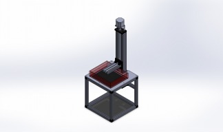
  1. Mysta

    Mysta New
    Builder

    Joined:
    Feb 23, 2017
    Messages:
    32
    Likes Received:
    1
    So I'm getting around 230ish + shipping for all the hardware parts..

    I assume this 'lcd control board' that's more limited isn't available anywhere yet

    Electronics would be:
    LED array(s)
    Ramps 1.4
    Pi?
    Powersupply?
    LCD
     
  2. nano

    nano New
    Builder

    Joined:
    Feb 11, 2017
    Messages:
    22
    Likes Received:
    0
    Fantástic info! could be possible work with uv led strip??
     
  3. evilc66

    evilc66 Journeyman
    Builder

    Joined:
    Jan 9, 2015
    Messages:
    392
    Likes Received:
    153
    Add to that one or more constant current LED drivers. I can make a few recommendation on that, but the final answer will depend on how the LED array is set up and the LEDs used.

    As for the adapter board, I haven't seen that sold separately yet, but I'm sure it's out there. At this point though, it's more reliable getting the LCD and the adapter board from the same source at the same time so that there aren't compatibility issues.
     
    #273 evilc66, Mar 1, 2017
    Last edited: Mar 1, 2017
  4. evilc66

    evilc66 Journeyman
    Builder

    Joined:
    Jan 9, 2015
    Messages:
    392
    Likes Received:
    153
    Probably not. They just aren't powerful enough to be able to get reasonable wattages under the area of the LCD. You would need to cram about 10 linear feet under the LCD, which I don't think you will be able to do. Anyway, you may run into thermal issues with that much strip in such a small area (the tape they are on is not a good conductor of heat, and with them being crammed together like that, they get pretty hot pretty fast).

    They way I'm going to do it will be with using the style of LEDs linked below

    10pcs/lot 1W 3W High Power UV Ultraviolet 365nm 375 395nm 400nm 410nm 420nm LED Lamp Bulb Light-in LED Bulbs & Tubes from Lights & Lighting on Aliexpress.com | Alibaba Group

    These can be glued down to a heatsink with the leads bent up slightly so that they don't contact the heatsink. Then you can wire them together by just soldering a small wire between the leads. My current plan is to wire them in a grid on 12mm centers in a 6x12 array (the the 5.5" screen).

    I think I may try some of the array style LEDs too, just to see how it works out.
     
  5. Mysta

    Mysta New
    Builder

    Joined:
    Feb 23, 2017
    Messages:
    32
    Likes Received:
    1
    So when looking for Array/LEDs what are things we're looking for for wattage and wavelength?(assuming hdx screen)
     
  6. evilc66

    evilc66 Journeyman
    Builder

    Joined:
    Jan 9, 2015
    Messages:
    392
    Likes Received:
    153
    A bit of background first about me. I've been working with high power LEDs for about a decade now, and have been implementing them into reef aquarium fixtures for about as long. Between my experimentation and being active in discussions on the forums I'm active on, I've acquired a fair amount of knowledge on the subject of LEDs and light.

    Normally, when looking at LEDs and how they will perform, I would be scouring datasheets to make sure that I pick out the best of the best, or at least, the best for the price. Unfortunately, short wavelength violet and UV LEDs get really expensive really quickly when it comes to high quality LEDs. That unfortunately relegates us to looking at cheap Chinese LEDs of unknown quality. Many times, vendors/manufacturers don't provide datasheets, and those that do often have incomplete or dubious data. So it's a bit of a crap shoot.

    At this point, the best approach without either spending a ton of time characterizing the LEDs or spending a lot of money on higher quality LEDs is just to brute force it. High wattage Chinese LEDs are very cheap comparatively. For that price, I'm kinda ok with getting an LED of somewhat unknown quality, as long as the wavelength is correct. I have a spectrometer that I can use to check that, so I'm not all that worried about it, but that's a tool that is out of the reach of most people (cheap ones are about $2K).

    So, what we can figure out is how much wattage per square centimeter of LCD space we have. Using the Duplicator 7 as a guide, we have a 120x70mm print area, and a 30W LED illuminating that area. That works out to 0.357W/cm^2 (screen is 84cm^2)

    Now, using the Slash3D as a guide for the usable area of the HDX screen (192x122mm), we have a screen area of 234.24cm^2. Apply the 0.357W/cm^2 to that and you would need 83.62W to achieve the same relative intensity (assuming that the HDX screen allows the same amount of light through). You could easily do that with a 100W 405nm LED, but I think a screen that big will have issues with light uniformity when used with a single light source.

    A better approach to a larger screen would be to use lots of smaller LEDs in a tight grid covering the area of the screen. It's more effort and cost, but the uniformity of the backlight will be much better. With the array about 3-4" from the back of the LCD, placing the LEDs on a 12mm or 1/2" grid should give pretty uniform coverage, especially if a diffusing film is used to help even things out. Now, to get the right wattage/cm^2, you would adjust the current supplied to the LEDs. A typical 3W class violet LED (violet is 400-435nm, UV is below 400nm) will run at about 3.4v at 700mA. That's 2.38W per LED. To hit the 83.62W mark, you would need 36 LEDs. To cover the area of an HDX screen using 12mm spacing, you would need 112 LEDs (14x8 array). If you ran everything at 700mA, you would have a 266W array. Now, there's nothing to stop you from doing this and having crazy fast cure times (and a ton of heat to deal with). If you drop the current down to 250mA, you would be right around the 83.62W target, but probably with higher luminous output due to the LEDs being more efficient at lower currents.

    It's also possible to make the array out of a few higher wattage LEDs. The larger LEDs will make getting the light distribution a little harder, but certainly not impossible. This way would reduce complexity and cost. 6 20W LEDs run at lower current in a 3x2 array would probably work fairly well.

    Of course, any of these approaches will require the use of the proper constant current LED driver, and a suitably big heatsink and fan.

    So, there's the long winded answer :)
     
  7. nano

    nano New
    Builder

    Joined:
    Feb 11, 2017
    Messages:
    22
    Likes Received:
    0
    Evil, did you see http://www.mouser.es/Search/Refine.aspx?Keyword=Cree+XP-E+royal+blue, seems great quality, perhaps expensive but there are a lot of options....

    About the leeds, which will work better, vilolet or UV?? im confused here, 405nm LED or 385nm LED????, about the array, i see any people working on arrays, and they insert resistances between the leds.....do ypu have any more ilustrative info about???

    My friend, i see this on the net....what do you think? Transparent LCD Touch Screen - See-Through Display | MMT Mirage
     
  8. nano

    nano New
    Builder

    Joined:
    Feb 11, 2017
    Messages:
    22
    Likes Received:
    0
  9. evilc66

    evilc66 Journeyman
    Builder

    Joined:
    Jan 9, 2015
    Messages:
    392
    Likes Received:
    153
    XP-E LEDs are some of the best out there. You can also look at the Cree XT-E royal blue, Luxeon Rebel ES royal blue, and Osram Oslon royal blue. All three of those have some of the highest efficiencies out there, as well as very high reliability.

    As for violet versus UV, it's really about the LCD. UV really isn't going to be a practical option, as shorter wavelengths of light are going to be blocked more readily by the LCD color filter and polarizer than violet would. Ideally, 460nm blue would give us the greatest efficiency, as the LCD was designed to pass this wavelength very well. Using just 460nm will limit our resin options to daylight cure only. Once we start to get down around the 405nm range, the absorbance of UV resins starts to pick up and can start to become an option, as we have seen with the Duplicator 7.

    As for adding resistance to the LED array, the reason they are doing this is because they are running multiple series strings of LEDs in parallel. The resistors are used at the beginning of each series string to help balance the current between each string. The problem with running in parallel is that every LED has ever so slightly different forward voltages when run at a particular current. Once you start making series strings of LEDs and putting them in parallel, you start getting differences in the total forward voltage of each string, and as a result, the current does not divide equally between each string. Adding in a small resistance can help to equalize the current in each string. It's not my prefered way of dealing with large arrays, but it requires fewer LED drivers and reduces cost.

    The transparent display concept looks interesting, but the size and resolution aren't too practical for our application. I'm sure they are horrifically expensive too.
     
  10. evilc66

    evilc66 Journeyman
    Builder

    Joined:
    Jan 9, 2015
    Messages:
    392
    Likes Received:
    153
    Those look good. Ballscrews and linear rails are always good things to have for accuracy. The Nema23 isn't really what's going to define your resolution. The ballscrew will have more to do with that, and with it being a 1204 screw (12mm diameter, 4mm travel per revolution), it will have higher resolution than the Openbuilds setup with the TR8*8 lead screw (twice the resolution actually).
     
  11. nano

    nano New
    Builder

    Joined:
    Feb 11, 2017
    Messages:
    22
    Likes Received:
    0
    Many thanks evil all days i leand any new, really you are a good teacher......;);)
     
  12. nano

    nano New
    Builder

    Joined:
    Feb 11, 2017
    Messages:
    22
    Likes Received:
    0
  13. evilc66

    evilc66 Journeyman
    Builder

    Joined:
    Jan 9, 2015
    Messages:
    392
    Likes Received:
    153
    That's certainly a good option
     
  14. nano

    nano New
    Builder

    Joined:
    Feb 11, 2017
    Messages:
    22
    Likes Received:
    0
    I found this ones....perhaps could work wel for arrays, and will be easy isntall it

    1pce envío libre 12 W 18 W 20 W 24 W 30 W 36 W 48 W Rectángulo Placa De Aluminio del LED/LED de Alta Potencia de Placa de Circuito/Placa de Calor PCB en de en AliExpress.com | Alibaba Group

    About the leds, really as i can understand with 460nm will work great with daylight resins, but not for Uv, this uv resins will need from 365 to 405nm for curing, im assuming that uv resins have more references and options than dayligth, but at this momenth which will the best option led to buy? on the link posted are a lot of diferent references:banghead:
     
  15. evilc66

    evilc66 Journeyman
    Builder

    Joined:
    Jan 9, 2015
    Messages:
    392
    Likes Received:
    153
    That looks like it could be a good platform to start an array with. There seems to be a number of boards that would work pretty well for the various LCD sizes we are looking at.

    Don't pay attention to the wattages referenced for each size. It's just assuming that a 1W LED would be used. Using a 3W LED will be no problem provided that the heatsink you place under the pcb is of sufficient size. There's no mention as to how the LEDs are set up, but it's almost a certainty that it's a series-parallel configuration. We just don't know how many LEDs are in series per parallel string.

    As to whether to go daylight or UV for the resin, it would seem that with the success of the Duplicator 7 with 405nm LEDs and UV resins, there shouldn't be much reason to not use UV resins. UV resins have the advantage of being more common, with more options for resin type (firmness, flexibility, etc...), as well as color. You can do clear, unpigmented resins with UV, but not with daylight resins.
     
  16. fernando palacio edreira

    Builder

    Joined:
    Mar 3, 2017
    Messages:
    6
    Likes Received:
    0
    Yes, i see that w are only for ilustrative purpouse, they are assuming 1W led, im looking for work on anything to convert the headsink on water coled, will ned any time and inspiration, but think will work best......

    At this time, will work with two 48w boards, 48+48 3w 405nm led, as i can exactly how many Leds are in series per parallel string, will need 300w led driver..

    The options here are several led drivers or one big..????

    @Evil, im thinking on your recomendation:

    -LG-24UD58 B - monitor de 24 Pulgadas 4K LED IPS (53.13cm x 29.89cm = 1587.9cm²) en 183.58 PPI, 0.1384mm

    0.138 could be sufficient for large pieces, but here with this lcd i cant use adapter board, neccesary will ned drive it with a pc and a good video card, dont know exactly if finally will be easy to configure the 3d printer or not on Nano DLP, will work?? will need help here.:(:(

    Thanks to all.
     
  17. Nomis

    Nomis New
    Builder

    Joined:
    Mar 4, 2017
    Messages:
    3
    Likes Received:
    0
    Hi Folks,
    I'm new here - just joined because I am interested in the idea of SLA printing with LCD and UV backlight. I think it's a great project and would like to try it myself sometime.
    If iI'm right the main obstacle is to get the UV light through the LCD, because most of the light is blocked by the color filters. I did find this paper and wondered if it might help:
    http://www.tnmsc.cn/down/upfile/soft/20110415/41-p210.pdf
    Maybe it is possible to remove the color filters using NaOH - this sounds simple enough but I bet it's more complex than that!!

    S
     
  18. Mysta

    Mysta New
    Builder

    Joined:
    Feb 23, 2017
    Messages:
    32
    Likes Received:
    1
    So there isn't really a pre-assembled array for the range we're looking for(that's not insanely expensive at least?)
     
  19. evilc66

    evilc66 Journeyman
    Builder

    Joined:
    Jan 9, 2015
    Messages:
    392
    Likes Received:
    153
    Two things with regards to the LED boards.
    1. The cheap Chinese LEDs that would go on these boards might have either the anode (positive) or the cathode (negative) electrically tied to the thermal pad on the bottom of the LED. This would create shorts if the thermal pads of all the LEDs were in direct contact with the pads on the board. When you get the LEDs, you will want to get a multimeter and check to see if there is continuity between the thermal pad and either of the leads coming out the side of the LED. You may also want to check to see if the thermal pads on the board are isolated from each other, as well as the aluminum board substrate. If the thermal pads on the board are isolated, then you can solder the LEDs down with a little thermal paste under the thermal pad of the LED without worry. If the pads on the board aren't isolated, and the thermal pad on the LEDs is common with either the anode or cathode, then you need to electrically isolate the thermal pads on each LED. You can use a thin layer of thermal epoxy that will be thermally conductive, but won't be electrically conductive provided that you don't push down on the LED too hard as you put it in place. Then you can solder the LEDs down.
    2. For the driver, you will need to find out how the LEDs are wired. For the 48 LED board, it could be wired as 4 strings of 12 in series, or 8 strings of 6 in series, or 6 strings of 8 in series. Each of those configurations would need a different LED driver as the voltage and current requirements are different. It may just be easier to order the boards and check how they are wired once they are in your hands. You could email the company, but it would suck if they told you one thing and it shows up configured a different way.
    As for the LCD, it's possible that you may be able to drive it with a Raspberry Pi through HDMI. Others have done it successfully with some tweaks to the system files, and it also seems that NanoDLP supports it too without any manual tweaks. If it doesn't work with the Pi (it's only a $35 experiment, so no big loss), then there are some small form factor PCs that may work. The newer Intel Atom CPUs support 4K output, and can be found pretty cheap. There were a few mentioned earlier in this thread. It seems that 4K over HDMI is more reliable over HDMI than DisplayPort (which is where I had issues and had to get a more robust machine). If you have to resort to the PC, then you can still use NanoDLP (they recently added Windows and Linux support), or Creation Workshop. Both will be able to interface with a Ramps or Grbl board over USB.
     
  20. evilc66

    evilc66 Journeyman
    Builder

    Joined:
    Jan 9, 2015
    Messages:
    392
    Likes Received:
    153
    Certainly an interesting read.

    Using sodium hydroxide (lye) looks to be the best option to the average hobbyist, as it's easy to get, and not nearly as nasty to handle as sulfuric acid (although it works faster). Something like this would require experimentation to see how long the LCD need to be exposed to the chemical to assure complete removal of the color filter. The iPad screen would be a good candidate there, as it's the cheapest screen by far, and also the easiest to get.

    My big concern is that lye will attack metals (all of the chemical options stated in that paper are metal etchants), including the contact points and ribbon cables for the LCD controller circuitry that's attached to the LCD with no easy way to remove them. Also, the LCD would have to be completely stripped from it's housing. Some of them aren't the easiest to get apart, and would required a steady hand to not break them on a regular basis. Can this be tried? Sure! Nothing wrong with a little experimentation. Is this a practical option for anyone looking to build a printer like this? Not really.
     
  21. evilc66

    evilc66 Journeyman
    Builder

    Joined:
    Jan 9, 2015
    Messages:
    392
    Likes Received:
    153
    Not that I've seen. Large arrays of violet or UV LEDs is a pretty specialized application, so they aren't that common. I'm sure that there are some companies in China that would custom assemble arrays for you for a small fee and a minimum order ;)
     
  22. evilc66

    evilc66 Journeyman
    Builder

    Joined:
    Jan 9, 2015
    Messages:
    392
    Likes Received:
    153
  23. Nomis

    Nomis New
    Builder

    Joined:
    Mar 4, 2017
    Messages:
    3
    Likes Received:
    0
    Hi Everyone,

    Please could I have your opinion on this product:

    ali-express link

    According to my quick calculations this has a pixel size around 85 microns, which I think is going to give a decent quality print :D
    Do you think it would be easy (or possible!) to use this in an SLA printer? The screen comes with driver accepting HDMI input so I'm hoping it could be used easily from a laptop or RPi?

    Cheers
    S
     
  24. evilc66

    evilc66 Journeyman
    Builder

    Joined:
    Jan 9, 2015
    Messages:
    392
    Likes Received:
    153
    Anything under 100 microns (0.1mm) is going to give pretty good results, and will have much finer detail than any FDM printer. That LCD will work fine (and the price is really good). I will warn you though about that vendor. That's the same place that I ordered the HDX and 5.5" 2K screen (noted earlier in this thread) with HDMI interfaces, and they have yet to ship my order after more than two weeks. Needless to say, I'm not happy. I even paid for expedited DHL shipping! Sadly, they are the cheapest source for a lot of these screens, so my hands are tied for now. I would proceed with caution. You may want to wait until I have my order in hand so that I can say whether it's worth the wait or not.
     
    Nomis likes this.
  25. Nomis

    Nomis New
    Builder

    Joined:
    Mar 4, 2017
    Messages:
    3
    Likes Received:
    0
    Thanks for the warning, I will wait for your advice after you receive the shipment!
    Currently I am planning to go with:
    • the above 10.1" LCD
    • an array of 24x 1W 460nm LEDs (future eden)
    • diffuser screen to even out the light before it hits the LCD (yet to find out where to source this one)
    • photocentric daylight resin
    • frame and z-axis from open-build parts
    • controlled with RPi w/ nanoDLP
    I've taken a lot of guidance from this thread, so thanks for the help everyone. If I do get round to ordering the parts and having a go at this build I'll feedback here too.
     
  26. nano

    nano New
    Builder

    Joined:
    Feb 11, 2017
    Messages:
    22
    Likes Received:
    0
    Hi,

    Today recibe my linear guide with Ballscrew and linear rail, seems good quality!!! the anly problem customs expenses....50€..:(:(

    Thinking about drive by a PC not sure, but what nwill be the best option Ramps or Grbl board?? seems ramps will be cheaper but what about final quality and resolution?? i see this two options..

    RAMPS 1.4 SB Premium

    CNC xPro V3 GRBL Controller Board – From Ooznest

    What do you think??

    Thanks !!!!!
     

    Attached Files:

  27. evilc66

    evilc66 Journeyman
    Builder

    Joined:
    Jan 9, 2015
    Messages:
    392
    Likes Received:
    153
    Make sure you check to make sure there is no end play in the ball screw. I'd hate to see that nice linear guide not work as expected due to poor setup.

    As for the controller, the Ramps and GRBL based boards will have about the same resolution. For something like this application, where you are only using the z-axis, it's really not going to matter much which platform you end up using. Ramps/Marlin and GRBL are both supported by NanoDLP. Ramps may have a slight advantage later on down the road though, as it deals with external devices better (things like shutters/LED control, resin level sensors, etc...)
     
  28. nano

    nano New
    Builder

    Joined:
    Feb 11, 2017
    Messages:
    22
    Likes Received:
    0
    Evil, i try to verify possible axial problems but seems all is ok, try to move on all possible directions and dont detect slack or displacements......:nailbite::nailbite::nailbite:

    Go will Ramps!!, the resin sensors will be very important, and perhaps could control the Temperature and fans
     

    Attached Files:

  29. evilc66

    evilc66 Journeyman
    Builder

    Joined:
    Jan 9, 2015
    Messages:
    392
    Likes Received:
    153
    Temperature is something that I have thought about. I haven't done any reading into it, but it would be interesting to see if the temperature of the resin changes the print fidelity.
     
  30. Mysta

    Mysta New
    Builder

    Joined:
    Feb 23, 2017
    Messages:
    32
    Likes Received:
    1
    So anyone done much with manufacturers? I'm considering paying the premium to get a custom led array at our desired power/wavelength and maybe trying to get a custom lcd without the filter.

    Also I have a few older tablets that are pretty low resolution(android tablet and a venue 8 pro) that I was considering tinkering with.
     
    Paul Stoller likes this.

Share This Page

  1. This site uses cookies to help personalise content, tailor your experience and to keep you logged in if you register.
    By continuing to use this site, you are consenting to our use of cookies.
    Dismiss Notice