Welcome to Our Community

Some features disabled for guests. Register Today.

OneZ i3

Discussion in '3D printers' started by Keith Davis, Apr 17, 2016.
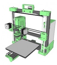
  1. Keith Davis

    Keith Davis Veteran
    Builder

    Joined:
    Dec 11, 2013
    Messages:
    506
    Likes Received:
    393
    Keith Davis published a new build:

    Read more about this build...
     
  2. Subramaniam S S

    Builder

    Joined:
    Apr 26, 2016
    Messages:
    16
    Likes Received:
    1
    Sir, its very nice 3d printer you designed, i planned to do the 3d printer same as like yours, can you send me details of the Z axis pulley(s) size, threaded screw size. etc and also in your CAD design i couldn't find the Z-axis screw mount and pulley mount details, In cad the screw was open on top but in your real printer you had something on top of the screw, can you send the pic of your printer(Z axis screw and pulley(s) mount).
     
  3. Keith Davis

    Keith Davis Veteran
    Builder

    Joined:
    Dec 11, 2013
    Messages:
    506
    Likes Received:
    393
    Thanks Subramaniam S S

    Top bearing size: 696zz
    Z axis threaded rod: M6x1
    Z axis pulley size: 6mmID x 20tooth on the M6 rods (6mm ID are hard to find, the BOM has a link to Robotdigg) but you can chuck a 5mmID pulley in a vise and drill it out to 6mm. I did that for the prototype and it's still printing...
    The arrangement is:
    1) M6 Acorn nut
    2) 6mm washer
    3) 696zz bearing
    4) Z-bearing-bracket
    5) 696zz bearing
    6) 6mm washer
    7) 6mm ID x 20 tooth pulley


    [​IMG]

    The Z-nut bracket has been changed in the SKP and STL zips. A M6 nylon nut (found in the BOM) is press fit into the bracket. A 3mm hole in the bracket is threaded for 3mm and a M3x8mm screw presses into the nylon nut to hold it in the nut recess.

    [​IMG]

    The z-bearing-brackets_z-nuts.skp & z-bearing-brackets_z-nuts.stl contain the bracket in the lower drawing.

    The pulley pushes up and holds the bearings tightly in the bracket, preventing the M6 screw from moving up or down. To align the left and right of the X axis, loosen 1 pulley and adjust the screws until X is level with the bed, then tighten the pulley.

    The misc-parts.skp contains a bracket that a standard dial indicator can be mounted to and the bracket fits into the slot on the extruder that holds the part cooling fan. Using a dial indicator for syncing the screws, then again for micro-adjusting the 4 adjusting screws on the build plate is accurate enough that I usually then just adjust the extruder height in the center of the build and print the first print with no further adjustments.
     
    #3 Keith Davis, Apr 26, 2016
    Last edited: Apr 26, 2016
  4. Subramaniam S S

    Builder

    Joined:
    Apr 26, 2016
    Messages:
    16
    Likes Received:
    1
    Thank you, In the new files there is no Y-MOTOR LID stl file and also in the assembly.skp, there is no belt and pulley(s) arrangement details for Y-MOTOR,also can i use "3D printer extruder w Fan duct all Metal J-head e3d v6 hotend RepRap aluminium" or "3d printer Hotend E3D v5 + Fan | 0.4mm nozzle, 1.75mm filament for Extruder".

    For the frame insted of 20x80 can i use two 20x40 bolted, will it affect pulley fixing ?
    Can i extend this whole system to 1000mm X 1000mm X 1000mm ?, if i am able to get all the components.
     
  5. Keith Davis

    Keith Davis Veteran
    Builder

    Joined:
    Dec 11, 2013
    Messages:
    506
    Likes Received:
    393
    The zip files have been updated. I also added to assembly.skp the two idler bearings for the Z axis belt.

    The first extruder link you have is to a bowden type, the second one to a direct type. You need the direct type. 3d printer Hotend E3D v5 + Fan | 0.4mm nozzle, 1.75mm filament for Extruder

    Here's a cutaway of what I use. The 1.75mm direct fin body has a 2mm hole. I drill that out to 4mm and fit a 4mmOD x 2mmID PTFE down to the barrel. At the top the PTFE is trimmed to fit snuggly against the drive gear and idler bearing. The PTFE is held in plasce by two set screws aligned parallel with the tube to keep it from raising during retraction. Heat from the barrel is dissipated enough before rising to the PTFE to allow 400C printing. The PTFE liner aids in printing PLA and Flex type filament. In fact, I replace the metal barrel with a PTFE (3mmODx2mmID) lined barrel for ABS, PLA, and Flex. PTFE lined barrels are sold separately for the sabove extruder.

    Extruder wise: We are not using E3D V6, but instead what is usually called a J-Head E3d V6. The difference is that the E3D barrels have 7mm threads and the J-Head clone has 6mm thread.

    [​IMG] [​IMG]

    You probably can use 2 40x20s if that's what you have. Don't consider how to bolt them together. In the OneZ-i3-assembly.skp you'll notice two 100x40 feet under the printer. The front hole is for a screw into the upright frame rail's center hole, the other two are for screw and slide nuts in the frame slots. Add two more holes so the foot is a bridge for your two 40x20s. Then, the 40x20 Y axis rail bolts to that frame using an OB L bracket on the front and a printed bracket in y-ends-idler.skp. Be sure to press the Y rail tight against your frame when tightening those two brackets. That should be adequate. But if you want, thread all of the centers on your two 40x20s and add holes to the psu-lid and the y-lid to screw those lids to the 40x20s.
     
    #5 Keith Davis, Apr 26, 2016
    Last edited: May 4, 2016
  6. Subramaniam S S

    Builder

    Joined:
    Apr 26, 2016
    Messages:
    16
    Likes Received:
    1
    Thank you, I ll start making and if anything i ll followup
     
  7. Keith Davis

    Keith Davis Veteran
    Builder

    Joined:
    Dec 11, 2013
    Messages:
    506
    Likes Received:
    393
    I'm shipping a partial kit to someone over the weekend so he'll be starting next week too. We plan on running Q&A here for that build also.
     
    #7 Keith Davis, Apr 27, 2016
    Last edited: Apr 27, 2016
  8. Keith Davis

    Keith Davis Veteran
    Builder

    Joined:
    Dec 11, 2013
    Messages:
    506
    Likes Received:
    393
    BTW, I see no reason why you can not extend to 1000mm. Here is a photo of a custom build I did for a 300x300 heatbed. Once running we didn't like the bowden dribble so I reworked it so the wiring all had plug-in connectors and Steve can convert to single direct drive by unplugging the wires - unplugging the bowden tubes - removing two screws / screw on the direct drive bracket - plud-in the wires. Takes him about 20 minutes to make the conversion. So, if you want to use a bowden setup, let me know, I have the SKP files for using a Chimera hotend.

    [​IMG]

    Also, my license prohibits anyone from building and selling OneZ on the open market. But that applies only to USA. If you should want to build and sell in India or anywhere in Asia, I would be happy to support that enterprise.

    I have also added the Marlin Sketch for the OneZi3 on Sainsmart 2in1. It's HERE
     
  9. Subramaniam S S

    Builder

    Joined:
    Apr 26, 2016
    Messages:
    16
    Likes Received:
    1
    Thank you, If you could send the details for changing from direct to bowden through SKP and STL It would be very helpful(We would decide based on availability). Also if possible can you post a video of oneZ i3 printing.

    and also will you ship worldwide ?
     
  10. Steve Jeppesen

    Builder

    Joined:
    Jan 21, 2016
    Messages:
    18
    Likes Received:
    1
    I have not had a chance to use the new OneZ i3/300 alot yet but I can say it seems to be a tad bit more quiet than the previous OneZ i2 I had been using the last few months. Currently still waiting for some supplies so that I'll eventually be able to print using Taulman nylon filament. I really like this design, nice and compact (as much as possible for a 300x300x300 printer!). It may present other problems but it would be nice if you were able to provide a color preference of the 3d printed parts to customers. I really like the gold parts, nice offset to the black parts.
     
  11. Keith Davis

    Keith Davis Veteran
    Builder

    Joined:
    Dec 11, 2013
    Messages:
    506
    Likes Received:
    393
    http://3dwrx.com/openbuilds/i3/i300-assembly-parts.zip
    The assembly is for a 300x300mm bed. Note that the Y axiz is longer and has a idler bracket at the rear like the one on the front. The parts skp contains just the parts unique to Chimera dual extrusion.

    Shot hastily just for you - I'll be making other vids next week for sales purposes....

    If you are referring to printed parts, I would, but I'm sure you can find someone local a lot cheaper and probably with shorter delivery.
     
  12. Keith Davis

    Keith Davis Veteran
    Builder

    Joined:
    Dec 11, 2013
    Messages:
    506
    Likes Received:
    393
    I have 4 in Peek Green mostly because the details show up really great in photos. I'm converting those two i2s to i3s in black (which do NOT display details well in photos). I plan to offer both for sale w/next day shipping. But for other colors I'd have to offer "custom" builds with a two weeks delay. Probably send them to PLA | ArchShield and let them fall in love with their choice. It's pretty good filament, wide color choice, in 1.75mm only, and consistent availability. Solutech's Apple Green was my real choice but they had availability problems until recently.

    Once you get to printing parts like the U joint be sure to post pics here, OK? That's a unique and elegant looking part.
     
  13. Subramaniam S S

    Builder

    Joined:
    Apr 26, 2016
    Messages:
    16
    Likes Received:
    1
    Thank You, Its nice!
    Sure i ll post the PICS
     
  14. Steve Jeppesen

    Builder

    Joined:
    Jan 21, 2016
    Messages:
    18
    Likes Received:
    1
    if a quote is not brought forward - kind of hard to tell who's replying to which post!

    Here's a snap shot of a U joint printed on a OneZ i2 in PLA which is not recommended for a final print that is for sure. This will more than likely be the single part that determines if a single wheel trailer can be 3d printed and functional/trustworthy.

    upload_2016-4-28_13-57-1.png

    Here's why you don't want to use PLA - the part in the above pic broke when I was removing the support material. We're looking at rotating the part and printing it to see if that will help as well as using Taulman Alloy 910 to print it with.

    upload_2016-4-28_14-2-34.png
     
  15. TechGirl

    TechGirl New
    Builder

    Joined:
    Jun 26, 2015
    Messages:
    27
    Likes Received:
    5
  16. Steve Jeppesen

    Builder

    Joined:
    Jan 21, 2016
    Messages:
    18
    Likes Received:
    1
    not sure of the size myself but the numbers on the belt are 860-2GT-6.
     
  17. Keith Davis

    Keith Davis Veteran
    Builder

    Joined:
    Dec 11, 2013
    Messages:
    506
    Likes Received:
    393
  18. TechGirl

    TechGirl New
    Builder

    Joined:
    Jun 26, 2015
    Messages:
    27
    Likes Received:
    5
  19. Keith Davis

    Keith Davis Veteran
    Builder

    Joined:
    Dec 11, 2013
    Messages:
    506
    Likes Received:
    393
    I have Assembly Instruction pages at ASSEMBLY It is for construction from scratch. An Assembly Instruction for a KIT will follow. This one is about half finished.
     
    TechGirl and Steve Jeppesen like this.
  20. TechGirl

    TechGirl New
    Builder

    Joined:
    Jun 26, 2015
    Messages:
    27
    Likes Received:
    5
    @Keith Davis I've had a look at the Assembly Instruction pages and for what it's worth I think they are very comprehensive with the exception of 7) Finish X axis, which doesn't seem to exist.
     
  21. Keith Davis

    Keith Davis Veteran
    Builder

    Joined:
    Dec 11, 2013
    Messages:
    506
    Likes Received:
    393
    That's a work in progress TechGirl. I'm on section 11 now. I just updated a few minutes ago.

    After I finish, probably tomorrow, I plan to go back through looking for inconsistencies, etc. I sold a kit to someone so I'm trying to keep ahead of him and using his feedback to tweak with.
     
  22. TechGirl

    TechGirl New
    Builder

    Joined:
    Jun 26, 2015
    Messages:
    27
    Likes Received:
    5
    I've finally decided, I'm going to build an i300. I have been looking for a good design and yours' is a simple as it gets.
    My current Prusa i3 is getting a bit long in the tooth, so once I've printed all the parts it will be full speed ahead on the i300.
    I'm going to use as much of the Prusa as I can salvage to cut down the cost.
     
  23. Steve Jeppesen

    Builder

    Joined:
    Jan 21, 2016
    Messages:
    18
    Likes Received:
    1
    I can't say how much help I can offer TechGirl but if you have any questions or anything I can help with let me know.

    With Keith's help I've learned how to print but that as far as it gets. I've got an interest in bldg a printer but nothing serious at the moment.

    My i300 currently printing calibration part

    https://goo.gl/photos/pDMmkkT9ChQHciUF8

    yes that is over to the right side of the bed and judging by how the back left corner is warping I can no longer put off leveling the bed.

    the printer traveled across country in the back seat of my car and I've never leveled it since getting it home. I've been able to print with it now for a couple weeks - over on the right side mind you but I've been able to print good parts.

    And many Thanks to Keith once again! I begged for him to post some instructions on how to level a bed with a dial caliper and he finally gave in! I had a heck of a time trying to level the i2 previously. Keith sent me a inexpensive dial caliper and tada I was up and printing that afternoon.

    Kudos to you Sir!
     
  24. Keith Davis

    Keith Davis Veteran
    Builder

    Joined:
    Dec 11, 2013
    Messages:
    506
    Likes Received:
    393
    @TechGirl I have one page left to do on the Assembly Instructions today (extruder wiring).

    I've changed to using only 200 step motors instead of two 400s for X & Y. The Sainsmart 2in1 can run 1/32 and a 200 @ 1/32 is smoother than a 400 @ 1/16 (and a 400 @ 1/32 has crazy Jerk problems and the equivalent of 200 @ 1/64 microsteps is overkill on a printer).

    Are you contemplating a dual/bowden or single/direct extruder?
    Have you purchased any motors yet?

    A word of caution on buying i300 parts - the build plate needs to be 13" x 13" because that is the size of the heat bed for a 12" build area. On Steve's I mistakenly ordered a 12" and had to extend the corners.
     
  25. TechGirl

    TechGirl New
    Builder

    Joined:
    Jun 26, 2015
    Messages:
    27
    Likes Received:
    5
    @Keith Davis, I will probably be using the motors from the Prusa which are all 200 step motors.

    I'm initially contemplating a single geared extruder mounted on the x-carriage (The Toranado Precision Geared 1.75mm Extruder - v1.1 by Toranado3D). The gearing of the extruder means that the Nema 14 motor is more than sufficient to drive 1.75mm filament.

    I also intend to use a 220V silicone heater bonded to a 5mm thick milled aluminium plate, milled on both sides to ensure flatness. Once I have the heater I will order the aluminium wide enough to allow for the mounting screws and also a similar 3mm aluminium sheet for the bedplate.

    As you might be able to tell, I've been thinking about this for a while.
     
  26. TechGirl

    TechGirl New
    Builder

    Joined:
    Jun 26, 2015
    Messages:
    27
    Likes Received:
    5
    @Keith Davis I have a couple of questions, why the different mix of stepper drivers? Would it matter if I used all DRV8825, of course the jumpers would have to change?
     
  27. Keith Davis

    Keith Davis Veteran
    Builder

    Joined:
    Dec 11, 2013
    Messages:
    506
    Likes Received:
    393
    Yes m'lady, I can see you've been contemplating this for some time :thumbsup:. I'm guessing you'll have other modifications along the way too....

    There is a widely held misconception that the drivers determine microsteps. They do not. The A4988 is capable of only full, 1/8 & 1/16 microstepping, while the DRV8825 is capable of full, 1/8, 1/16 & 1/32. The number of jumpers determine which microstepping the driver will use (RAMPS does not have the fourth 1/32 jumper and using a DRV8825 will not give RAMPS 1/32 microstepping - regardless of what the intertubes might tell ya).

    You certainly can use DRV8825 for all 4 motors. Doing so would not change the jumper set-up. I mixed driver in the ASSEMBLY only so if someone had A4988s they would see they are not appropriate for all motors and to emphasis the directions of the potentiometer screws.
     
    #27 Keith Davis, May 4, 2016
    Last edited: May 4, 2016
  28. Steve Jeppesen

    Builder

    Joined:
    Jan 21, 2016
    Messages:
    18
    Likes Received:
    1
    I suppose my offer of questionable assistance earlier was odd TechGirl, but as far as I am aware, I have the only i300 in existence today. Yours would be the 2nd when completed.

    After leveling bed and fine tuning some settings, printing up a bunch of 0.1mm layer height parts for a set of vr goggles

    https://goo.gl/photos/j1gGmvocjrZ7FojS8

    upload_2016-5-4_21-35-19.png
     
    TechGirl likes this.
  29. TechGirl

    TechGirl New
    Builder

    Joined:
    Jun 26, 2015
    Messages:
    27
    Likes Received:
    5
    @Steve Jeppesen I appreciate the offer of assistance. I'm sure I will have questions as I go along, but for the moment I'm just gathering infomation and the necessary parts to start building.
     
  30. Keith Davis

    Keith Davis Veteran
    Builder

    Joined:
    Dec 11, 2013
    Messages:
    506
    Likes Received:
    393

Share This Page

  1. This site uses cookies to help personalise content, tailor your experience and to keep you logged in if you register.
    By continuing to use this site, you are consenting to our use of cookies.
    Dismiss Notice