Welcome to Our Community

Some features disabled for guests. Register Today.

Warnke CNC Router

Discussion in 'CNC Mills/Routers' started by JP Warnke, Jan 21, 2017.
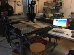
  1. JP Warnke

    JP Warnke New
    Builder

    Joined:
    Jan 4, 2017
    Messages:
    32
    Likes Received:
    10
    JP Warnke published a new build:

    Read more about this build...
     
    drxlcarfreak likes this.
  2. stargeezer

    stargeezer Journeyman
    Builder

    Joined:
    Feb 20, 2015
    Messages:
    328
    Likes Received:
    117
    Hi JP. Looking at all you give us so far, that's going to be a beast! But even so, I doubt steel will be possible.

    Am I reading into the drawings that the gantry is made up of 15 series 8020 extrusions?
     
  3. Florian Bauereisen

    Florian Bauereisen Well-Known
    Builder

    Joined:
    Feb 24, 2014
    Messages:
    188
    Likes Received:
    60
    Hi,
    as it seems you have researched a quite a bit, but right at the start:
    Steel - doubtful (depending on strategy)
    Budget: if you really plan to spend that much on it than something is terribly wrong.

    About
    1) Yes - either use a far bigger extrusion or ad an L shaped aluminum to it and use multiplex wood to the back (wood is goodf absorbing vibes)

    2) Yes always couple two axis or use quality servos ... or, as i would suggest, go for a more conventional format, there are reasons for the way they are build

    3) forget about the weight - these ball screws take it and actually weight figures fare less into performance or wear than you`d think.
    So for a short machine as it is now 16mm will be all good, on a longer mill 20 mm to go for because of whip-
    But the 20mm screw will now steal you some performance - fare more than the weight of your gantry. To counter that by going Nema34 sized steppers is not the best either as both the screw and the motor now have increased inertia and thus torque requirement.
    So your mill might be not as springy as you would like it to be. Solution is to go longer motors instead of thicker ones if you need.

    5) Increasing z is the most difficult, just look up professional milling centers offered in different sizes. Z increase is most expensive compared...
    Aditionally you should turn your z-setup around :
    Keep the wagons stationary opposite your beam, and use the rail to further stiffen the z- bracked. Also use another pice to make the z bracket either U- or at least L shaped to stiffen it up ( you did that sort of on your side plates)

    How much z do you really need? on a regular basis? why not slice the parts? fare more waste sensible anyway and faster to mill.

    6) Closed loop will not prevent anything if your setup is totally off, while a good stepper setup will not loose steps. So a big enough power supply high voltage and sensible tuning (accellereation, maxspeed steps per mm ) is more important.

    Btw looking your machine bed, especially your extrusions on the short axis - they are made for air mainly?
    On my mill i use 90 x 90 mm super strong type ones weighting some 17 kg/m and my mill wasn`t build for milling steel.
    Get bigger ones.

    Just a few pointer - hope that helps a little

    greets

    Flo
     
    DeepK7 and JP Warnke like this.
  4. Florian Bauereisen

    Florian Bauereisen Well-Known
    Builder

    Joined:
    Feb 24, 2014
    Messages:
    188
    Likes Received:
    60
    Forgot:
    Stepper power the ball screw actually acts as a gearing, my 2N/m servo on x ( long axis on my cnc) pushes at aprox 80kg - two grown man would never ever stop the gantry. (20/5 mm ball screw) definetly more than a 2,2 kw hv spindle could ever throw at it.
     
  5. JP Warnke

    JP Warnke New
    Builder

    Joined:
    Jan 4, 2017
    Messages:
    32
    Likes Received:
    10
    Hey Star. 45 Series Minitec. Im not sure what the cost comparison is for 8020 (i used to use them all the time ...i think i have a pdf of their per unit profile costs actually if someone wants one; though its a few years old). I've been using minitec at work lately though; and i had the profiles loaded in my CAD library already; hence minitec!

    It will hopefully be rock solid. I know using linear rails and ball screws gets pricey (not to mention the cost of materials; as we will have steel fabs and alum tooling plate in some areas); but we really wanted to invest in building something great that will last, that will be fun to machine with and that will make nice clear smooth cuts. The risky side is - not having done this before - we risk missing the mark in some areas (which could get even pricier!). Even though we both have machining/cnc/design experience there are some items here we def need to do a lot of reading on now to make our money count!
     
  6. JP Warnke

    JP Warnke New
    Builder

    Joined:
    Jan 4, 2017
    Messages:
    32
    Likes Received:
    10
    Thats good to know on the ball screws. I figured these things would be strong. I have seen other dual drive machines with 5/8" ball screws, so i figure not really any difference between these and 16mm.

    We were concerned about that the motors as well though. We are now thinking we might go up to 34s.

    I did like a lot of the stuff on cncrouterparts. We had actually been originally considering getting the nema23 4-axis plug & play setup from them, but we recently changed course and began looking at building up our own controls. My pappy has worked up a rough list of goodies we are thinking about (from automationtechnologiesinc.com):

    - (5) NEMA 34 640 oz-in Stepper motors (KL34H280-45-8A)
    - (5) KL-5056D Digital Bipolar Stepper Motor Drivers - 32 bit DSP based
    - (6) Motor cable connectors
    - (1) Handwheel MPG (wireless) for Mach 3 controller, 4-axis (X, Y, Z, A)
    - (1) Water Pump 200 GPH for spindle cooling system
    - (1) 2200w 3HP Water cooled CNC Milling Spindle,KL-2200
    - (1) 2.2Kw (3HP) VFD for Spindle (KL-VFD11) 110VAC input, Connect R and T
    - (1) Unregulated linear 960W/48 VDC/20A Toroidal PSU (KL-4820) with 5VDC
    - (1) CNC 6-Axis interface breakout board with relay and spindle control
    - (1) 24V 2A Switch power supply.
     
  7. JP Warnke

    JP Warnke New
    Builder

    Joined:
    Jan 4, 2017
    Messages:
    32
    Likes Received:
    10

    Thanks Flo

    On budget - if we can save and spend less; then Im definitely all for that! If you're saying you think we will go way over that, then..... : (!!! In our case we have access to machine shop and machine shop tools; i have connections to controls engineers for help, good water jet & fab vendors, etc. Much of the machining we will do ourselves (minus jetting), so cost-wise we are ok there. It's mostly just going to be paying for raw materials, fasteners, electronics, etc. with about 250-$300 of water jet work. 5-7k is really the budget cap range. If we can do this thing, work out the bugs and make it function the way we want for less than 5, then ill be thrilled.

    On answers to my ?s:

    1) - Wow...thats a weird thought! 90x180 seemed so strong already! Minitec doesnt make a larger one X-{ So...if we went with the L/wood setup you're suggesting - is it like an L-bracket hanging off the top with a solid piece of soft wood like pine against the backside of the extrusion? Would sandwiching thin rubber/urethane or foam inbetween the extrusion and a piece of soft wood help any further? I just really don't want chatter on cuts to be an issue at all. Makes me wonder if i shouldn't try for a 4' width X-(!

    2) - When you say 'couple' two axes? Im not understanding? I do have motor couplers on each side of y ball screws (is that what is meant here?). Do i need also to somehow tie these sides together underneath with a crossbar or pulley setup (like i've seen done on smaller cncs with a single Y-drive motor in the center)? If i can avoid that id prefer to; but if i have to redesign to tie across from bracket to bracket, id rather do that than deal with major racking issues later on.

    3/4) - Good to know on the ball screws. So you're saying it might not be best to move up to NEMA 34s for this machine? But to go for lengthier 23s? Right now we have 420 oz-in 23s. If we went up to 640 oz-in Nema 34s though with the 16mm ball screws, this would be better, yes?

    5) Well...i don't absolutely need the 12" I guess; but the big hope with it was the ability to use a rotary axis (we may be receiving a 10" ish tall rotary axis from someone; so if i can find a way to use it on this machine; that'd be awesome. It's not a necessity, but it'd be really cool if i could make it work). Because of the height on that rotary, we were thinking (man...it'd be cool to do some artwork on 10-11" ish rounds on a rotary if possible). Im new to a lot of this; so im probably being a hopeless dreamer; and i will probably have to learn the hard way <: ), but if there is a way to accomplish the height and maintain the rigidity, i'd love to be able to pull it off. If it's asking for trouble and enough people tell me "nOOOOOOO!!! Don't do it!!!!" Then Ill def listen X-)

    I did change my z around some this evening also anticipating it would be better to spread the rails though (although i did not go opp sides - think it would be better to do it that way or better to spread the load top and front as i have here??):

    new z.JPG


    6) Thanks. I will need to read up some more on this stuff still.

    As far as the machine bed - there were some items i did not show before that might help some more?? :

    here is the full machine pic at present:

    newiso.JPG

    Capture underside.JPG

    I have front/rear water jetted 1/4" steel plates with a bunch of holes into my sandwiched profile stack. The profiles arent 90x90s, but the table top is 19mm thk over a 45mm thick (45x90 pc) over another 45x90 pc (at least on front and back), . The side pcs shown are 45x135s. I will be gussetting it like crazy underneath to try to I will probably consider going to 90x90s though around the base though. If i can't cut thin sheet steel with this, it's ok. I didn't count on it (just would have been a cool perk).

    Anyhow, thanks so much for input!

    -JP
     
  8. Florian Bauereisen

    Florian Bauereisen Well-Known
    Builder

    Joined:
    Feb 24, 2014
    Messages:
    188
    Likes Received:
    60
    Hi,
    On 1) Did not realise 180x90 ( did not look close enough) -that should suffice, but i meant just wood for dampening..
    2) use belts ... look up a german site: mixware..p3 cobra just pics is enough to understand
    3) in general it is better going longer motors if needet... but as said the ballscrew acts as a gearing, I run 2Nm servos on mine and it will rip your arm off. Your 2,2 kw will hardly generate any cutting forces to speak off, so i guess some 4-5 Nm will suffice (gut feeling) easy.Too lazy to calculate.
    5) for strong or steel your z setup is wrong! y´spindle hangs about a wobbly plate, the further extendet the worse. If you after stiff turn it round, Simple as that. Machine will be only as good as the weakest link so if you leave z like that you are going to cut butter but not steel!
    6) looks better , still your extrusion is 3 strong parts stacket atop each other connected by thin walls, These extrusions come in light strong and super strong, use super strong. Yes these don`t come off ebay abut whats a saving of say 100 alltogether if you end up with a machine that doesn`t satisfy?
    Bosch, Item sell them...you will even get specs for them and these are build within Tolerances...

    gottta run offf to work now

    Flo
     
    stargeezer and JP Warnke like this.
  9. stargeezer

    stargeezer Journeyman
    Builder

    Joined:
    Feb 20, 2015
    Messages:
    328
    Likes Received:
    117
    On the last couple CNC Router builds I've used this for control - High-Torque Stepper Motor, Stepper Motor, Driver, Stepper Motor kit, DC Servo Motor, DC Servo Motor kit, Stepper Motor Power Supply, CNC Router, Spindle, and other Components. Stepper Motor | Stepper Motor Driver | CNC Router | Laser Machine | 3D Printers For Sale

    It REALLY makes a huge difference for motion control and it has 6 axis support in case you do a 4th or 5th axis without losing you spindle control, like some of the Chinese breakout-boards. If you need more control inputs or outputs, you can add another breakout board and an additional jumper cable to address port 2 in addition to port 1. Using a Ethernet port instead of a parallel port makes using a newer computer easier.

    I first tried this combo when I had built a control box that seemed to have interference problems that I just couldn't sort out. I'm still not certain that I didn't actually have a computer problem, but whatever the cause was, changing to these two boards solved all problems. So when I started my 1x1 1/2 meter machine I started with this. I really had problems believing that it would make that much of a difference - but it did.

    I also think I'd up the y axis steppers to something in the 1100-1200 ozin range like High-Torque Stepper Motor, Stepper Motor, Driver, Stepper Motor kit, DC Servo Motor, DC Servo Motor kit, Stepper Motor Power Supply, CNC Router, Spindle, and other Components. Stepper Motor | Stepper Motor Driver | CNC Router | Laser Machine | 3D Printers For Sale

    Of course, all this is just my opinion.
    Larry
     
    #9 stargeezer, Jan 23, 2017
    Last edited: Jan 23, 2017
    JP Warnke likes this.
  10. JP Warnke

    JP Warnke New
    Builder

    Joined:
    Jan 4, 2017
    Messages:
    32
    Likes Received:
    10
    2) So here is a video of the P3 Cobra I found in action: Looks like just one central stepper pulleyed to 2 ballscrews on either side. Seems like that would definitely get rid of any racking problems; but i guess then im wondering - I've seen other people build these without a crossbar on the underside, and with the dual steppers as i have - for example:

    Capture1.JPG
    Maybe these designs typically less dependable for heavier gantries like the one im making though?

    I may rework my design to use a tie bar. I'd rather not if there is a way to make it function well without tying it across underneath; but if other builders like yourself really think it would be best; ill probably pursue a redesign there.

    5) I totally agree. I am working up some strengthening gussets on the back side of the floppy spindle plate.

    6) Ill check into bosch and 8020 (have used both before) but i know minitec has a good product as well. Ill select something about that size that is the most rigid (and straight/flat).

    Thanks!

    -JP
     
  11. Florian Bauereisen

    Florian Bauereisen Well-Known
    Builder

    Joined:
    Feb 24, 2014
    Messages:
    188
    Likes Received:
    60
    Yes, vid clearly shows that one single stepper is powerful enough even for two screws. If you only found the vid than you missed the site i mentioned and thus do not realise the P3 probably is the very best designed kit money can buy. check yourself
    Comparing that to that whimpy cnc in the pic below and calling it more heavy is a joke is all i can say. ( you did not check the site - did you?)
    Just look at those round rails .... a clear indication of cheapo and by design not able to haul heavy loads. Get yourself some specs of even just 15 sized square hiwin wagons ... no need to say anything further.
    Have you seen any of those flimsy designs milling something else than a v-carve sign in mdf?

    If you do not use a tie bar , your gantry will go into parallel twist- especially if you plan a wide setup. period. Relying on a couple of screws and braces on your x-beam or even the accuracy of microstepping- yes? thats what your after? maybe you better read up how microstepping works and while at it machinery design.
    People constantly dreaming/ asking for steel ( driving a porsche) but do not want to listen or spend money ( id rather buy a pinto - it is exactly as good as a porsche).
    Funny how you never hear from them again after finishing their cnc. NO vid of fame - no bragging - nothing... how comes? well maybe companies offering 1-50 Ton machines for milling steel probably just do not know about round supported rails, flimsy gantries and extralight extrusions, -they just rip their customers off their money?
    Or do we agree that if we try to build an aluminium machine able to cut into a harder material (steel) than we just need any and every trick to make it happen? And needing to use the right milling strategy still.

    I do not want you to build a machine for me ( my design) - design it yourself, that is whats it all about...but turning around your z to have the rail on your spindle plate doesn´t cost a dime and is another step towards a stiffer machine. I did not ask for steel - you did.
    I`d understand an unwillingness if i suggest expensive mods - but free ones? Guess, once more i waste my breath so to speak. Make your own mistakes, i tried..

    greets

    Flo
     
    #11 Florian Bauereisen, Jan 23, 2017
    Last edited: Jan 23, 2017
  12. stargeezer

    stargeezer Journeyman
    Builder

    Joined:
    Feb 20, 2015
    Messages:
    328
    Likes Received:
    117
    There is a much simpler solution to racking problems than using a tie bar. If you place an limit switch on both y axis screws, you can use Mach 3 to zero those two steppers independently of each other. Eliminating any need for a tie bar - each time you zero the y axis, any racking is eliminated.

    When I get back home in a few days I'll look up some links that show you how to do it. It's very simple.
     
    JP Warnke likes this.
  13. JP Warnke

    JP Warnke New
    Builder

    Joined:
    Jan 4, 2017
    Messages:
    32
    Likes Received:
    10
    Whoa : |. ......take it easy....

    I'm not rejecting denying or even questioning any of your good advice. I'm just trying to understand the reasons for doing something one way or another and what you mean by what you say in some cases (and it sounds like you werent reading what I had written or understanding what I meant in a few areas as well; that's ok - it happens).

    I AM a machine designer and I certainly don't claim to be a genius but I fair well enough to provide for my little family. I try my best. I was not provided with money for a great education so I've had to work and read in my spare time to learn as best I can. Matter of fact the money my father and I have for this is only due to his business sale (and again I plan on saving as much as possible; it's just we have budgeted for 5-7k maximum). There is no need to look down on someone else who doesn't know something you may know, right?


    Anyway; Nobody can know everything. I won't berate you for your English if you don't berate me for not understanding building CNCs as well as you do. fair enough? : )

    I'm just here to learn. I haven't ordered anything yet (except my ball screws). I fully confess I may be shooting for the moon with my z height - but I'll remind you that I'm not fixed on doing it exactly this way; that's why I'm asking for advice - and I do appreciate your advice and I certainly have been considering it (if I did not give you that impression I can promise that was not my intention).

    Anyhow, thanks again.

    Best regards

    -JP
     
    Rangatang likes this.
  14. JP Warnke

    JP Warnke New
    Builder

    Joined:
    Jan 4, 2017
    Messages:
    32
    Likes Received:
    10
    Thanks Star. That'd be helpful.

    Do you think because of the height and width on my gantry i may want to consider a tie bar anyway? (I got the impression Flo was thinking it would be necessary in this case?). I just know I've seen other 4' gantry spreads that don't tie together at the base; and I'm wondering if they still work well. Seems to me like your motors are the same you can set one up and just sort of loose the coupler on the other to get it in tune?
     
  15. stargeezer

    stargeezer Journeyman
    Builder

    Joined:
    Feb 20, 2015
    Messages:
    328
    Likes Received:
    117

    I don't think she was saying that, but I'll go back and re-read the posts.

    I would never try to tie the gantry ends together. I looked at the you-tube videos of the P3 and I think that is a design with a lot of potential. It does address the biggest problems with keeping the two screws in sync with one another, but at the cost of cutting your power to each screw in half. To keep all things equal, you would need to double the rating of the y axis stepper motor. (I've got a few 1850 ozin steppers I'll sell :) )

    Now, as for loosening a coupler and letting one stepper pull it along - can we just agree that there are things you can do and they might even work after a fashion and sound good on paper, but you'll never get the machine to actually work that way? This is one such in my opinion. Trying to operate a CNC with one side of the y unpowered is just not going to fly. As soon as you try to engage a cutter into any material, the unpowered side is going to twist and flex at every joint.

    Flo is right on about any efforts cutting steel. Go out and find a used Bridgeport for a couple thousand and forget cutting steel with this. I get why you want 12" clearance under the gantry, but it's really cutting into your usability. The spindle is going to swing like the pendulum in my grandfathers clock. The closer to the work piece the gantry mounting point is, the greater will be its strength.
     
    JP Warnke likes this.
  16. JP Warnke

    JP Warnke New
    Builder

    Joined:
    Jan 4, 2017
    Messages:
    32
    Likes Received:
    10
    So on the Ys you're thinking don't tie them together? Or do? Guess I'm confused because in the P3 cobra vid here they are tied across the bottom with a plate. Are you saying 'p3 model is a good one to mimic in terms of the Y-action/y-motors/ballscrews'? Or you think that whil it's good, the dual ballscrews/dual motors setup I have on Y right now will be still be good and that I just need to bring my gantry down a few inches and get the spindle mounting less floppy?).

    I'm thinking that's how I'll move forward here; I'll take my gantry down a few inches; shorten the Z ball screw and gusset my spindle plate to keep it from swinging like your grandfathers clock pendulum : ). If I lose the ability to mount a rotary I guess that ok.

    I'll just not cut steel with this. I think that much is clear at this point X-}. No steel. Alum though?; id def like to handle aluminum on occasion.

    I think I'll go to nema 34 640 oz in for the Ys (and X) instead of the 23 420 oz in ones I have currently. Unless it really is better to use longer nema 23s? I guess I don't understand the advantage of a long 23 over a short 34 of the 34 still has a higher torque rating? Would the motor windings along the longer axis in the 23s help with control/accuracy maybe?

    Thanks!
     
    stargeezer likes this.
  17. stargeezer

    stargeezer Journeyman
    Builder

    Joined:
    Feb 20, 2015
    Messages:
    328
    Likes Received:
    117
    If you really want to try the method used in the p3 cobra, I'd say go for it, but my personal gut feeling is that it's a solution in search of a problem. I do think it addresses a couple issues but it also opens up a few too. If I were you, I'd get this first machine built and running using tried and proved methods and then if you want to play around with some outside the box ideas, you have time and tools to build a test bed. I've always said that the best tool to build a CNC mill is a CNC mill.

    The motors and ballscrews you have are fine, except I'd up the y axis steppers. The NEMA23 425 stepper motor will work fine for the Z axis. They should work for the X axis too, but going with a 34, 940 +/-ozin motor. On my 1mtr square machine with a 2kw spindle motor, I'm running NEMA23's 425ozin in all positions, but I'm using 1/2" 5 start screws, so the loading is not as high as it would be with your setup.

    Before I start this next part let my first say that I can't look these numbers up right now. So if I'm off on my exact numbers please forgive me and offer a correction. I'm working from memory.

    As to stepper length, My experience is the longer a motor is, the more power it consumes. As you look at the specs on stepper motors you'll note that the inductance ratings are quite varied within a given physical dimension. This is important to give you a feel for the use of the stepper. If it has a low inductance rating, it will give you less torque but will give you a higher useable RPM range. The higher inductance the motor is rated for will indicate a high torque number at lower RPM range. It's all about the number of windings and the length of those windings. For example, a NEMA17 motor that's body is 65mm long has a potential of generating 68 ozin of torque. I also have some NEMA 34 that have bodies that are 65mm long but have a rating of 240 ozin. The additional power of the 34 over the 17 is directly linked to the increased diameter of the motor. Bigger diameter = more wire in motor = more power. That's why the NEMA 34 1850 ozin motors I have are the size of a football!

    On your machine you are using ball screws which I think are 1605 which give you some where around 10mm of movement per revolution. That's a pretty fast screw, so you'll want motors that output more torque than RPM. On my mill with the 1/2in acme screws because the screws are 5 start I do get a bit more movement per RPM than a single thread acme screw, but not so much that I need to jump up to a NEMA 34 to make up the difference.

    I hope that makes sense and I hope my numbers are close enough you get my points.

    Fingers crossed, back to you,
     
    JP Warnke likes this.
  18. stargeezer

    stargeezer Journeyman
    Builder

    Joined:
    Feb 20, 2015
    Messages:
    328
    Likes Received:
    117
    I forgot to answer about cutting aluminum. Yes. If you can drop the gantry down a few inches and shorten the Z movement it should do fine with AL. Bear in mind that none of these machines will compete with any CNC you have run in industry. Where you might have seen endmills cutting .250" per pass in a vertical milling center, these could be maxed out cutting .020 per pass IF everything is perfect.

    The biggest thing in your favor is that you are building such a heavy machine. But like Flo said, it's only as strong as it's weakest link. That link for this build is that z axis.
     
    JP Warnke likes this.
  19. JP Warnke

    JP Warnke New
    Builder

    Joined:
    Jan 4, 2017
    Messages:
    32
    Likes Received:
    10
    Thanks for all the input! I've reworked this thing; shortened it up 4" and up-sized the motors to those 34s. I still need to work out my Z bracketry and do a bunch of tedious fixes and what not; but it's getting there bit by bit.

    I definitely feel better about the height drop. I think I will still be able to find a way to mount the rotary actuator off this as well (its 12" tall, but I will probably build a sub-plate that can hang off my table to set the rotary on and get the axis down further. It's not a central desire to get the rotary working, but I'm satisfied with this idea; If I can still get 7 or 8" dia. work pieces on a rotary with this, that'd be awesome.
     
  20. stargeezer

    stargeezer Journeyman
    Builder

    Joined:
    Feb 20, 2015
    Messages:
    328
    Likes Received:
    117
    I've just had time to glance at your newest design mods, it looks awesome. I really like the redesigned Z axis and the position of the Y axis rails to be as close to the gantry level as possible. Using a box frame for y axis is smart and I hope you can include some construction details and a materials list as the design finalizes. Your choice of stepper motors seems very appropriate for you updated design too.

    Great job JP!

    Larry
     
    JP Warnke likes this.
  21. JP Warnke

    JP Warnke New
    Builder

    Joined:
    Jan 4, 2017
    Messages:
    32
    Likes Received:
    10
    Thanks! I will try to remember to post a build list when I get this thing all worked out!

    I did find out my father ordered 5mm pitch for these ball screws instead of the 10mm ones. I guess that's ok. It will be better for control, just slower travel. I'm casually considering moving up a bit yet on my motor length because of this.

    ...Think I'll stick with the 34, 640ozin ones for now; but if I'm dissatisfied later it I can switch them out.

    right now I'm just working in a bunch of the details. Fit spacers all over the place and hole patterns and detail prints and getting quoting on a few things.

    I had a water jet vendor my co. uses give me a ballpark of about 250-300 to jet my end pieces and all 20-30 so fit spacers out of a 1/4" pc of 1020. I was ok with that; although I'm thinking I'll see how much it would increase if they jetted the clearance holes out as well. I'm guessing it will double : |.

    I'll try to post some machine Pic updates in a few days.

    Best Regards,

    -JP
     
  22. stargeezer

    stargeezer Journeyman
    Builder

    Joined:
    Feb 20, 2015
    Messages:
    328
    Likes Received:
    117
    Any progress JP? :)
     
    JP Warnke likes this.
  23. JP Warnke

    JP Warnke New
    Builder

    Joined:
    Jan 4, 2017
    Messages:
    32
    Likes Received:
    10
    Hey Star. Yep. Design is pretty much done. We received our linear rails the other day (they looked good). I've got my extruded alum being quoted right now. The bulk of my other details will be jetted or plasma or laser cut. Getting quotes on those.

    I'm detailing everything right now. Hoping to start cutting parts within a few weeks (lot of it depends on our jet/plasma/laser vendor. Those guys are always swamped and I don't want to pay the higher premium for faster delivery. I'm ok to wait.)

    Hopefully I can start posting some build pics within a month or 2 here!
     
  24. JP Warnke

    JP Warnke New
    Builder

    Joined:
    Jan 4, 2017
    Messages:
    32
    Likes Received:
    10
    And we just cut an order for the minitec and another order to laser cut most of the steel pieces for this.

    That will comprise a lot of the pieces/items seen in the pics here.

    Good progress being made.
     
  25. JP Warnke

    JP Warnke New
    Builder

    Joined:
    Jan 4, 2017
    Messages:
    32
    Likes Received:
    10
    Most of my mechanical items are on order. I have a fasteners list and maybe about 5 plate details i will need to get some stock for; other than that i have just about everything else on its way....minus controls

    To be honest; this is a daunting area....we only know enough controls-wise to be dangerous (like...not in a good way, hah). I mean; i know what i need (ish), but i dont feel comfortable just ordering a breakout board and a bunch of drivers and motors and everything i need unless i know it's going to work together nicely (and me never having done this before seems a recipe for problems).

    They make pre-built kits (i know - was thinking about getting this with a 5th driver option), but they're like 2x the cost of building your own.

    Anyone have any recommendations on good, clear, videos or tutorials i can read up on to help me design my own controller kit? Or is that just a bad idea for a first timer; X-)?
     
  26. Rodm

    Rodm Well-Known
    Builder

    Joined:
    Jan 3, 2017
    Messages:
    121
    Likes Received:
    42
    I know the feeling. I'm doing something similar to the video below. I plan to add pause, restart,abort buttons and a controller board made by Kyo. I've heard good things said about the g540 a bit more expensive than some setups with individual componants but makes the wiring a bit easier. One disadvantage is if it breaks down you can't just r&r onemail piece.


    CNC Controller
    This is a link to Kyo's website - g540 controller board
     
    JP Warnke likes this.
  27. JP Warnke

    JP Warnke New
    Builder

    Joined:
    Jan 4, 2017
    Messages:
    32
    Likes Received:
    10

    Nice. And for about 90 bucks on the box, that works out great!

    Unfortunately i won't be able to squash all my stuff in one of these :|. all Nema 34s, dual y-drive and we wanted the option for a 5 axis. Think it's going to be pretty pricey X-( ...Its so tempting at this point just to buy a pre-built package....but the cost is a good motivator to do it the hard way. X-)
     
  28. Rodm

    Rodm Well-Known
    Builder

    Joined:
    Jan 3, 2017
    Messages:
    121
    Likes Received:
    42
    Yep, way to small! I had your build confused with another I've been following. I've seen a few builds where an old computer case was used. Some of those old towers are huge. Good luck! It will be a great machine.
     
    JP Warnke likes this.
  29. stargeezer

    stargeezer Journeyman
    Builder

    Joined:
    Feb 20, 2015
    Messages:
    328
    Likes Received:
    117
    I was going to second Kyo's video's too. He has done an excellent job making everything clear for non-electricians. He is also the man who has helped me to actually solve any problems I've experienced.

    Have Fun!
     
    JP Warnke likes this.

Share This Page

  1. This site uses cookies to help personalise content, tailor your experience and to keep you logged in if you register.
    By continuing to use this site, you are consenting to our use of cookies.
    Dismiss Notice