
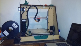
IntroductionI'll start with a little eye candy! This is a short video of the QuorXZ in action.
This video (Part I) focused on the mechanical operation of the printer. (There is a Part II which focuses on the print quality and is the end of the same print job.) This was one of the first prints (and in PLA), and was before I mounted the RAMPS to the case or did any cable management. It looks much better now, prints better and faster, and has been refined a bit since then (upgraded extruder, added heated bed, and various other tweaks). It will now also print ABS, Nylon, and hopefully some flexible filaments (not tried, but soon...).
So I'm guessing you might be concerned about the string drive....
Why you might consider building one anyway...
The QuorXZ was inspired by the engineering and prototype design of Nicholas Seward, which is documented at RepRap.org: CoreXZ . There were several questions posed about the reliability and consistency of his design, and his answers convinced me to give it a try.
The thread linked above is well worth reading in depth, but I'll can tell you the results of my experience here very briefly. I've been printing with this printer for almost 2 years. I've not needed to adjust the XZ string tension in over a year and a half. (I added a heated bed last year - so had to restring Y.) I've moved the printer several times during that time. And it still prints much better than the MakerBot, and at least as good as the Ultimaker 2+ we had at work. (And it's definitely more versatile than either one.)
BuildAbout the Files
The files included in the "Files" section consist of 4 zipped folders and an Excel spreadsheet. 2 of the folders contain the OpenSCAD source files, and the other 2 contain the DXF files for cutting, and the STL files for printing. (See the 00readme.txt files in each folder for more information.)
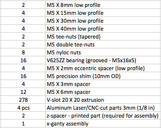
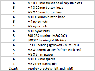
The Excel spreadsheet, QXZ-BOM is a detailed bill of materials for what you need to build a working printer. (This file is also included in the "Parts" section.) I have tried to make the spreadsheet as complete, thorough, and easy to use as possible. Page 1 is a master parts list organized by type (screws, nuts, etc). Page 2 is a "buy sheet" organized by vendor with clickable links (in most part) to the exact part needed. For some eBay stores, if you need to search for a part, use the exact "Part Description". Page 3 is a "build sheet" organized by assembly (and order to be assembled). I recently spent a lot of time organizing and checking these to make them as accurate and helpful as possible. Use page 2 to buy your parts (and label them as they come in), Keep page 3 beside you when you build (and pay attention to the comments).
No photos are included in the Files section. I took a lot of photos, but I didn't take photos of every step. The photos I do have will be included in the build directions below and will hopefully be sufficient.
If you decide you want to give this a shot, then buy your parts (we can call that "Step 0"), and let us begin...
Step 1: Assemble the Y-Gantry and Print Bed
I originally designed this to use the 216x216 OpenBuilds build plate, and you can use that option with an aftermarket print bed if you want. It will work without modification, and the directions will be the same (but using only 4 V-wheels). However, I recommend going with the designed plates instead. It allows a slightly larger print area, and will make it much easier to add a bed heater later if you want. (The drive strings run all the way around the assembly, blocking access through the sides. This gantry plate has large openings for easy access for wiring through the bottom of the plate.)
You will need the following parts.
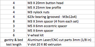
Note: It is OK to build the assembly with the corner nuts on the top instead of the bottom. That's how I did it when I added a heater to my bed (see notes and photo at the bottom of this step).
- Assemble the 6 V-Wheels: Press a bearing in one side and flip over, place 1 shim and press the other bearing into place. Set the remaining shim and the nut aside. Assemble the stacks for the smaller (5mm) holes on the gantry plate: Set a M5x25 screw on its end, add the bearing, add a remaining shim, add a 6mm spacer. Place the exposed screw through the 5mm hole and affix with the M5 nut. Tighten completely. Repeat for the other two holes.
- Assemble the stacks for the larger (~7mm) holes on the gantry plate: Set a M5x25 screw on its end, add the bearing, add a remaining shim, add a 6mm eccentric spacer with the small end up. Place the exposed screw (and eccentric spacer) through the 7mm hole and affix with the M5 nut. Adjust the marking on the spacer to face the outside. Tighten only slightly. Repeat for the other two holes. (Note: This puts the nuts on top of the gantry plate, instead of beneath the v-wheels - you could do it the other way.)
- Place the gantry on the test piece of 20 x 80 v-slot extrusion and adjust the eccentric spacers (all in the same direction) until the motion is smooth with no wiggle at all. Fully tighten the nuts, check again and adjust if needed. Remove the gantry from the v-slot and set the v-slot aside.
- Attach the print bed to the gantry plate: Place the 4 M3x20 screws through the corner holes of the print bed and flip over and rest on a flat surface with the screws pointing up. To each screw add a 3mm spacer, add a 623v bearing, add another 3mm spacer. Flip the completed gantry (wheels up) and place over the 4 screw ends. Add the M3 nuts and tighten completely. This completes the print bed build. Set the print bed assembly aside.
I don't have a photo of the print bed assembly by itself, but here are a couple of images as to what it should look like and how it fits.
Important notes about a heated bed option (and adjustability):
In the photo above you will notice the important mechanical feature is keeping the Y string-path on a single plane. It doesn't really matter how high the actual print bed is above that plane (other than losing a bit of Z-height print capacity). When researching string-drive and heat, I became concerned that heat from a heated bed might affect the string tension. I use a mat-type, rubber insulated heater mounted beneath the upper print plate. After adhering it to the plate, I covered it with some thin fiberglass batting, held in place and covered with some reflective aluminum tape. I replaced the upper bearing spacers with M3 lock nuts (about the same depth as spacer), and added a 6mm long section of 1/8" inner-diameter rubber tubing (compressed to about 4mm) to raise the bed, and provide leveling adjustability. The lock nuts are important to keep the bearing from "floating". I also added a 3mm borosilicate glass plate on top of the bed so I can use (and easily clean) glue stick to help adhesion. I've lost about 7mm in print height, but I've had no problems with heat (I often heat the bed to 110C), and I can fine-tune my bed leveling. (Note - the glass is "behind" the front bolts, so I've lost about 10mm of Y as well.) If you do use a heated bed, you may also need to "widen" the lower notch on the center section of the case to allow the cables to pass freely without contacting the carriage or wheels. I widened mine on one side to about 10mm away from the printed Y-bracket string guide.
Step 2: Assemble the Case and Fixed Rails (Y & Z)
If you get your case parts before your other parts, you can go ahead and assemble most of the case while you wait. I strongly urge you to pick up a 24" x 18" craft/sewers mat to build on. The lines will help you keep the case perfectly square while you are building.
You may not want to do this, but I actually used wood glue on all of the mating vertical pieces. (Don't glue the top piece!) Be careful with assembly. The side pieces of the case are not identical or symmetrical. (There is a front and back and a left and right to the finished case and it matters.)
You will need the following parts.
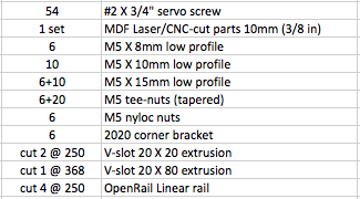
Note 1: I ordered my linear rail in 500mm lengths, so that I only needed to make 1 cut in any piece. (It also made for a smaller shipping package.)
Note 2: It might be easier to install the z-rails (Step 2c below) before assembling the case. However, I will document below how I did it so the photos match more closely.
2a: Assemble the Case
- Lay out the parts as shown in the first photo below. The center vertical section is symmetrical, but the stepper motor holes go at the bottom. The side pieces are not symmetrical and there is a left and a right: The left side has the stepper hole near the top, and it should be "in front" of the center section. The right side has the stepper mount holes near the bottom, and they should also be "in front" of the center section. The long slot in the top piece should be "in front" of the center section. The narrow front and rear case pieces are identical.
- Assemble the tabs in the center section to the slots in the side pieces first. Add the top piece and temporarily secure with masking tape. Add the front and rear piece and temporarily secure with masking tape.
- Square up the assembly, and drill pilot holes with a 1/16" bit through the third 2mm hole from the bottom and the 2mm hole below the top slot of the side pieces - into the center section (drill about 1/2" depth). Use 4 #2 screws and fasten the sides to the center securely through these 4 holes.
- Check square, and drill pilot holes through the 2mm holes in the tabs at the front and rear of the side pieces - into the slots of the narrow front and rear case pieces. (Make sure to hold the front and rear pieces firmly against the side pieces when drilling.) Use 4 #2 screws and fasten the sides to the front and rear pieces securely through these 4 holes.
- Check square, and drill pilot holes through the 2mm holes in the ends of the top piece (on each side of the slot) - into the tops of the side pieces. Use 4 #2 screws and fasten the top to the side pieces through these 4 holes. (Note: mark top or bottom of the top piece so it doesn't accidentally get flipped in later steps. It will be removed often during the build.)
- Square up the assembly, and drill the remaining pilot holes (you can wait on the remaining top pilot holes till later).
- (Optional) If you are going to glue the vertical seams, now is the time to add the glue. Remove the screws on one side of the case at a time, add the glue and replace. Important: Do NOT put glue on any surface that will touch the top piece - it must remain removable for maintenance of the printer!
- Check square one more time, and finish fastening the sides and front and rear pieces with sufficient #2 screws. Don't put screws in the top two holes of the side pieces yet.
This is the FRONT of the printer.
2b: Assemble and Install the Y-rail
- Mark and cut a 368mm length of 20x80 V-slot extrusion. You might verify the mark against the case before cutting. You want the rail to be flush with (or slightly short of) the outside of the case. Don't cut it too long.
- Attach the corner brackets to the V-slot. Insert 1 tee-nut in each of the center two rails, Insert 2 tee-nuts in each of the outer rails. (All of this on the same side of the extrusion.) Use 6 M5x8mm screws to attach the 6 corner brackets barely tight. The flat side of the 4 brackets on the outside slots will face outward and be >10mm from the ends. The flat side of the two center brackets will face the center section of the case and be positioned on the "front side" of the center section.
- Place the rail on the case assembly (making sure the two center brackets are in front of the center section). Insert 2 M5x15mm screws through the front of the case and into the brackets. (The nuts will go inside the brackets.) Slide the case over the edge of the work table, and reach underneath to get 2 M5 lock nuts started (don't tighten yet). Repeat this at the rear of the case. Once you are sure the rail is centered and flush at the front, push each bracket solidly against the inside of the case (pushing the nut and screw in the front hole with it enough to get your driver in for the rail screws), and completely tighten the rail screws. Then, completely tighten the M5 nuts on the case screws. Repeat this process for the rear screws. Finally fasten the two center brackets by placing M5x15mm screws through the brackets, through the MDF and fixed with M5 lock nuts on the back side of the center section. Tighten case and rail screws completely.
- Check the printer and rail for square and level and adjust these screws if necessary before continuing.
2c: Assemble and Install the Z-rails
- Mark and cut 2 250mm lengths of 20x20 V-slot extrusion. Mark and cut 4 250mm lengths of OpenRail linear rail.
- Insert 5 tee-nuts into one slot of one 250mm length of V-slot. Space ~50mm apart.
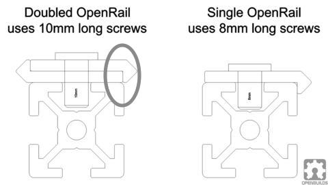
- Double two of the linear rail pieces, inside to inside (see first image below), and affix to the V-slot using 5 M5x10mm screws. Take care to make the ends flush with the V-slot. These doubled rails must be firmly squeezed together (side to side) while tightening. Also, because of the elongated screw slots in the linear rail, care must be taken to align the edge of the rail, exactly parallel with the side of the V-slot. I suggest aligning the rail seam (shown circled below) with the V-slot face on one end, and tightening the screw on that end completely. Flip around and align the same seam with the same face on the other end and tightening that screw completely. Double check, and completely tighten the remaining screws. Repeat the process on the other Z-rail.
- Place a mark 100mm to 105mm from the printer bottom (the table top) on the back of the case center section on each side of the wide opening. This marks the bottom of the Z-rail. (105 is the correct measurement from the design, but mine are set at 100. If you have raised your bed for a heater, use 105 max.)
- Lay the case on one side to install the first Z-rail. Insert 5 tee-nuts into the V-slot side opposite the doubled linear rail - spaced ~50mm apart. Hold the the rail against the back of the center section, flush with the case opening, and the "bottom" end on the mark. Fasten to the case with 5 M5x15mm screws. Tighten snugly but don't over-tighten. Flip the case over, and repeat for the other Z-rail.
- Set the case back upright, square, and adjust to make sure each Z-rail assembly is at the correct height, and that the V-slot face is flush with the inside of the center section cutout. Only snug the screws as these will probably need to be loosened later when installing the XZ-gantry assembly. The second photo below shows one of the rails installed. (Sorry - best picture I had of this step.)
- This completes the Case/Rail assembly. Set the assembly to the side (or on the floor, out of the way).
Step3: Assemble the X-Gantry
I'll start this step with a motivational image. This is the completed X-gantry from the rear, and I could lie and say it was photographed from the bottom, but....Just because I installed my gantry upside down doesn't mean you have to (the eccentric spacers are easier to adjust if they are on top).
You will need the following parts.
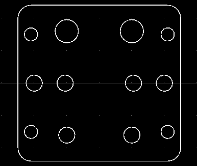
- Find the 50mm squarish aluminum part with twelve holes. Orient it as shown in the first image below. I will call the row with the two largest holes "the top row". If one side has a better finish than the other, orient it facing forward. I will call that "the front".
- Install 4 M3 rivnuts in the 4 middle holes. Insert the rivnuts from the back of the plate. To afix the nut firmly into the plate, You have to "balloon" the front of the rivnut to force the part in the hole to expand. Ideally, you should use a rivnut tool, but you probably don't have one. Find a steel (stainless best) M3 bolt with a wrench hex-head and full threads. Screw the bolt, through the front until the threads are all the way engaged through the rivnut. Put a M3 lock nut on the end and tighten completely. Using two wrenches, tighten the bolt and nut as much as physically possible (without letting the rivnut push out through the back at all). This will take some elbow grease. Remove the bolt. To test that the rivnut is secure enough, use an ordinary M3 screw and tighten it, exerting about the pressure (or a little more than) you would use to hold the hot-end holder. If you've printed the hot end holder, you can use it to test with. If the rivnut doesn't spin, it is good to go. If it moves at all, use the other bolt and crank it down some more. You should be able to see at least a slight bulge in the rivnut. See the second image below for the plate with rivnuts installed.
- Assemble the 4 mini V-wheels. Press a bearing in one side and flip over, place 1 shim and press the other bearing into place. Set the remaining shim and the nut aside.
- Install 2 V-wheels in the two center holes in the top row. For each one, place a M5x25mm screw through the front of the plate, and from behind the plate, add the 6mm eccentric spacer (small end toward the hole), the left-over precision shim, the V-wheel, and finally the M5 lock nut. Adjust the spacer so the mark faces upwards, and snug the nut.
- Install the remaining 2 V-wheels in the two center holes in the bottom row, following the same procedure, but use a regular 6mm spacer and tighten the nut completely.
- Place the gantry on a length of 20x20 V-slot and adjust the tension like you did on the y-gantry. Turn the eccentric spacers at the top of the gantry (in the same direction) until there is smooth motion, but no play in the gantry. Tighten the nuts completely, and remove the gantry form the V-slot.
- Manufacture and install the string adjuster screws. I couldn't find a M4x25mm long screw with a smooth shank, so I used 30mm screws and cut them to 25mm. That's also why I used the acorn nuts (completely cosmetic) to hide the rough end. You could use ordinary lock nuts and let the uncut screw "stick out" - I just thought it was ugly. In any case, you will need to drill a 1/16" hole through the shank about 4-5mm from the screw head. (Depending on your tools, you may need to also manufacture a drilling jig to accomplish this.). Using a larger bit and/or some abrasive, carefully debur both sides of the hole. Prepare the M4 lock nut (create threads in the nylon) by putting it on the screw the correct way, and "working" it on the threads for a bit. (You probably want to do this before cutting the screw.) Remove the nut and mount it on the screw "backwards", leaving ~6mm of thread exposed. Insert the screw with nut into one of the remaining holes and affix the M4 acorn nut. Adjust the screw so that the hole will be over the slot in the V-slot. Repeat for the remaining screws. (You can actually do this entire sub-step later when you get ready to string the "instrument".)
Note: The 4 remaining M3 screws are for holding the printed hot-end holder. You can go ahead and mount that loosely now if you have it.
Step 4: Assemble the Z-Gantry (Creating the XZ-Gantry Assembly)
This is probably the most complex assembly of the build. You will want to make sure you have installed all spacers, screws, nuts, plates, etc, in the correct order, and that everything is in the proper orientation before the assembly is installed on the printer. The good news is that you can leave everything sort of "loose" until you install the assembly. I don't have photos of intermediate steps, but if you study the photos in this step carefully, you can pick out all of the parts.
This is the REAR of the Assembly
This is the FRONT of the Assembly
You will need the following parts.
Note: You could install the XZ-Gantry assembly now, but it will be easier to install almost all of the string guide bearings first. You may end up wanting to freely move the case around while you are doing the string guides, and the gantry would just get in the way. If you do attempt it, you can leave the XZ-Gantry suspended with a string. (That's actually what I did. I did it because I was concerned about adjustability and fit - you don't need to because I already did it. It fits!)
- Mark and cut a 278mm length of 20x20 V-slot extrusion. This is the X-rail.
- Gather the remaining aluminum plates. You should have 2 large parts and 2 small parts. The large parts will be mounted on the rear of the X-rail with the tapered end pointing toward the center of the printer. The small parts will be mounted on the front of the X-rail with the flat side towards the outside of the printer. (See photos above.) Build one end, and repeat the sub-steps below for other end (after adding the X-gantry).
- Attach the large plate to the X-rail. Insert a double tee-nut in the V-slot, place the printed spacer above it (with the molded side against the rail and flush with the end), place the two holes of the tapered end of the plate above that, line up all the holes, and fasten with 2 M5x15mm screws. Tighten only snugly as these will be adjusted when the assembly is installed.
- Flip the assembly over to rest on the plate. From underneath insert 2 M5x30mm screws in the outer holes. (These are oversized to accept the eccentric spacers in the next step.)
- Build the bearing stacks on the exposed screws. On each screw, add the following in this order: M5 low-profile eccentric spacer (spacer side down), M5 precision shim (10mm OD), grooved M5x16x5 bearing, M5 precision shim, M5x6mm spacer, grooved M5x16x5 bearing, M5 locknut. (See second image below.) Tighten only slightly beyond finger-tight. These stacks will need to be a bit "floppy" later when the assembly is installed. Set the assembly aside.
- Build the bearing stacks on the small plate. Place 2 M5x40mm screws through the outer holes of the small plate, and lay the plate on the screw heads. On each screw, add the following in this order: M5x6mm spacer, M5 precision shim (10mm OD), grooved M5x15x5 bearing, M5x6mm spacer, M5 precision shim, grooved M5x15x5 bearing, M5x3mm spacer. (See third image below.) You can put a nut on this temporarily to keep the parts in place until the next step (just in case you are clumsy like me...)
- Attach the small plate to the large plate and x-rail. Put a single tee-nut in the end of the V-slot on the side opposite the large plate. With the small plate stacks facing up (and nuts removed), place the rail assembly with large plate (new tee-nut side down) over the stacks and carefully guide the screw ends into the two remaining holes on the large plate. Affix with 2 M5 lock nuts and tighten only snugly. Flip the assembly over, and fasten the small plate (through the center hole) to the rail with a M5x8mm screw into the tee-nut. Tighten only snugly. This completes one end of the Z-gantry.
- Add the completed X-gantry assembly to the rail from the opposite end, and with the X-gantry plate on the same side of the X-rail as the small Z-gantry plate. Repeat the steps above to install the other end of the Z-gantry. That will complete the XZ-Gantry assembly. Set it aside until installation.
Step 5: Assemble the String-bearing Guide Paths
As preparation for this step, you might want to re-view the introductory video. It shows all of these parts in action. This step is divided into two sub-steps: The Y-motion guide path, and the XZ-motion guide path.
You will need the following parts.
5a: Assemble the Y-motion Guide Path
The photo below shows the left Y-bracket (the sting-anchor bracket). The right side is similar but has no anchor pin (the strings go all the way through it instead).
5b: Assemble the XZ-motion Guide Path
- Prepare the printed brackets. The M3x10mm screws screw directly into the plastic. Before you add bearings, "create threads" in each of the holes by screwing the screw into the hole firmly. Don't over do it, one time is enough.
- Sandwich a grooved M3x10x3 bearing between two M3x0.5mm spacers, and press the sandwich into the slot of the bracket, aligning the stack with the holes. (You may need to use a small steel rule and/or an ice pick to get the spacers in far enough and centered with the holes.) Put the M3x10mm screw down through the top hole, the spacers, and the bearing, and screw into the bottom hole of the plastic. Repeat this with the other three bearings (including the other bracket). Check that the bearings move fairly easily, and adjust tension by tightening or loosening the screw.
- For the left bracket, cut the M5 zither tuning pin to 23mm (cut the bottom), and taper the cut with a dremel or file. Insert/twist it into the hole. This is a friction-fit pin and it should be fairly tight when fully inserted into the hole.
- Mount the Y-brackets to the Case. For each backet, use 3 M4x20mm screws through the bracket and into the 3 holes in the center section next to the wide notch. (The brackets mount to the front of the center section.) Affix with M4 lock nuts and tighten securely.
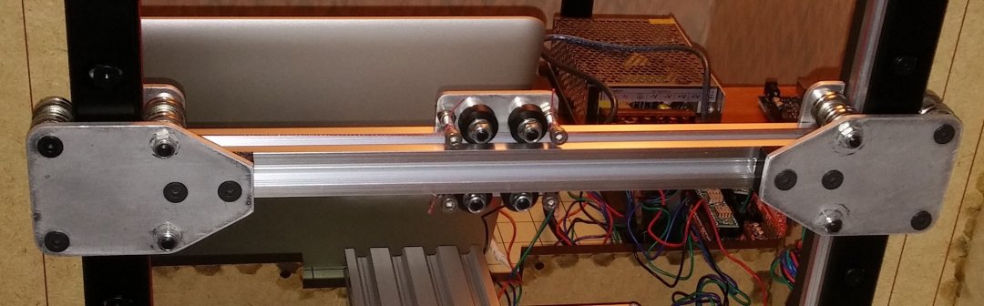
The XZ-motion guides consist of 8 posts, each holding a spacer (to bring the path into the proper plane), and two bearings mounted back to back to create a small "V" to hold the string. There are 4 large-diameter guides at the top and bottom of the Z-rails which guide the sting around the ends of the Z-rails. The other 4 guides guide the string from the stepper motors into the required vertical paths necessary for the XZ motion. The photo below shows the guides and the string path (along with the stepper spools). We're getting close!
This is the BACK of the Printer
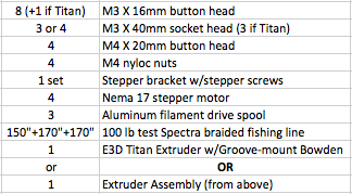
Step 6: Assemble the Extruder (if using the printed extruder)
- Install the 8mm posts and bearings. For each of the 8mm holes in the center section, insert a M8x40mm screw from the front side of the panel. Add one M8x3mm spacer, 2 M8x22x7 bearings, and a M8 lock nut. Tighten securely.
- Install the lower 10mm posts and bearings. For each 10mm hole below the Z-rails, insert a M10x40mm screw from the front side of the panel. Add one M10x2mm spacer, 2 M10x26x8 bearings, and a M10 lock nut. Tighten securely.
- Don't install the two upper bearing posts at the top of the Z-rails at this time. That space needs to remain clear to install the XZ-Gantry in the final assembly step. You can go ahead and put the spacers, bearings, and nuts on the 2 screws and set them aside to use later. This completes the string guide path assembly for now.
Skip this step if you are using the E3D Titan Extruder (highly recommended). Both extruders will fit with the 10mm case and the steppers listed in the stepper assembly step. I built the QuorXZ with the printed extruder. (In fact, I designed the extruder specifically for this machine.) I only switched to the Titan about a month ago. If you are pinching pennies though (like I was at the time), this extruder works well with PLA and ABS. I want to print with flexible filaments and I'm not sure how well this one would fare.
This extruder consists of 4 printed parts: The case, the cover, the lever, and the thumbscrew.
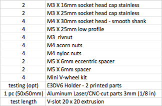
You will need the following parts.

- Press fit the M5x10x4 bearing into the cover and set aside.
- Assemble the case. Use a 2mm or 5/64" drill bit to clean the filament path in the case (two holes - top and bottom). Tap the hole in the "top" of the case for the M5 push-fit connector. I used a 10-24 self-tapping screw that seemed to work OK. Screw in the push-fit connector. You may need to use padded pliers to get it all the way in. Drop the M4 barrel nut into the 8mm hole with the threads facing the slot.
- Assemble and install the thumbscrew with spring. Drop the M4 spring into the top of the printed thumbscrew. Drop the M4x30 wrench-dive bolt into the thumbscrew. Screw the M4 bolt (with thumbscrew) into the barrel nut in the case and set assembly aside.
- Assemble the lever. Sandwich the M5x16x5 bearing between 2 M5 precision shims (10mm OD) and press the sandwich into the slot of the lever, aligning the stack with the holes. (You may need to use a small steel rule and/or an ice pick to get the spacers in far enough and centered with the holes.) Place a tee-nut with the "nipple" against the plastic in the tee-nut indentation of the lever, and hold it there while you insert and start the M5x15mm screw from the other side. Tighten securely.
- Stack the extruder on the M3x40 screws. Place the lever (in the closed position) against the case with the hinge joint nested properly. Set the case-lever assembly on the cover in the proper orientation (the cover will only cover the case in one position). Thread the M3x40mm screws through the cover and the case (you may need to use a driver to get them through the plastic). Drop the MK8 hobbed gear into the cavity to keep everything together for the next step, and set aside.
(I used the other 3 screws in my new Titan!)
A brief interlude: I love the sound of 3D printers! They're like little singing robots with accompanying instruments. I mention this because we're getting very close to "stringing" this particular instrument. (And we will even "pluck" the strings to help adjust tension.) Now even though I love the sound, not everyone in the house does. I did add a couple of things to slightly attenuate the sound. I used thin cork spacers to mount the motion steppers (don't do it on the extruder stepper - no space.) After the printer was complete, I added some thin, 1/4" wide foam insulation tape to all of the bottom case edges. These steps are completely optional for preference and are not mentioned further in the build. The QuorXZ sings pretty softly for an open-frame printer. I love listening to it!
Step 7: Assemble and install the Stepper Motors and Extruder
This step will be in 3 parts: Preparing the motion steppers by wrapping the spools, Installing the motion steppers, and installing the Extruder and it's stepper.
Note: When attaching steppers, consider the positioning of the stepper cables to avoid interfering with the string path and other parts. Looking at the front of the case: My Y stepper cable is against the inside of side case. My right XZ stepper cable exits on the left side. My left XZ stepper cable exits on the top. My extruder stepper cable exits on the bottom.
You will need the following parts.
7a: Prepare the Motion Steppers (Wrap and attach the spools)
7b: Install the Motion Steppers
- You will need to cut 3 lengths of the 100lb test fishing line. 150" for the Y-spool, and 170" for each of the XZ-spools. You will also need some masking tape. Each of the spools has 2 offset holes on each end. The larger hole goes all the way through the spool. The smaller hole is a feeder hole to the spool surface. To wrap a spool, insert the line into the larger hole and pull half of the length through. Take an end and feed it through the smaller hole, and start wrapping. (It doesn't matter if you are left-handed or right-handed - wrap in the direction that gives you the most control.) Wrap from the outside edge of the flat to the center of the flat. Take care to pull tight and not have any overlap of wraps. When you are done, you should have a single layer of string filling half of the spool, and a long tail left over. Use some tape to hold the line in place (try not to get too much tape on the bare part of the spool - you'll remove it soon. Flip the spool around, and wrap the other end using the same hand motion, to meet your previous wrap. Your tails should leave the spool in opposite directions. Remove the tape, back off one wrap from each side, and tape across the length to hold everything in place. (I taped around the smaller end as well.). You will have to remove this tape near the end of the stringing process, so make sure you can access it easily. Repeat the process for all three spools and mark the tape on the Y-spool.
- Attach the spools to the stepper motors. You will be able to reach the set-screw on the Y stepper after it is installed, so the distance is not too critical. Set it with the base of the spool about 10mm from the face of the stepper, and tighten the set screw enough to keep it from falling off. (Be sure and use the Y-spool.) For the XZ steppers, the set screw will NOT be accessible after installation. The outer edge of the wide rim of the spool (where it starts transitioning down toward the spool surface) must end up "plumb" with the back surface of the case center section (these steppers themselves will be on the front side). To set this, put the spool on the stepper and lightly tighten the set screw against the flat on the shaft (it should slide with a little pressure). From the front of the case center section, fit the spool into the opening and hold the stepper firmly against the case. Push or pull the spool until that transition point lines up with the case. Carefully remove the stepper and spool and crank down the set screw. Repeat for other stepper.
7c: Install the Extruder and it's Stepper
- Return the XZ steppers to their slots, double-check the spool alignment, and fasten each with 4 M3x16mm screws. (Be sure the string tails are clear of the hole.)
- Attach the Y stepper to the Pololu mount. The L-shaped Pololu mount will be mounted upside down to the case. (i.e., the case part will point down vertically, with the stepper mount on top horizontally.) Insert the stepper, spool-down through the stepper mount hole and fasten the stepper from underneath with the screws included with the Pololu kit. (The mount should not be attached to the case yet.)
- Attach the Y-stepper/mount assembly to the case. Hold the assembly inside the case, and push 4 M4x20mm screws from the outside of the case. Affix with 4 M4 locknuts and tighten securely. If you are finding it hard to get tools in there, it's OK to temporarily remove the spool.
- Adjust the height of the Y-spool. The center of the Y-spool (where the string comes off) should be at the same height as the bearings in the installed Y-brackets. Eyeballing is probably close enough. Loosen the Y-spool set screw, set the height, and tighten securely.
Note: This build publication is not quite finished. I was having trouble with the editor in draft mode, so I published it early to see if that would help. I will finish it as soon as I figure out how.
Thanks for your patience.
Scotty
QuorXZ: A String-driven, Core XZ Printer
Build in '3D PRINTER BUILDS' published by Scotty Orr, Aug 31, 2017.
The QuorXZ doesn't magically appear. It's gestation takes time, careful attention, and requires many parts. However, when it is ready, a magical, mechanical instrument is born....(and when you finally say its name, it sounds a little bit like "corks").
-
-
Build Author Scotty Orr, Find all builds by Scotty Orr
-
- Loading...
-
Build Details
- Build License:
-
- CC - Attribution NonCommercial - CC BY NC
Reason for this Build
I started with a small One-UP 3D printer, upgraded it, modified it, and was still not satisfied. I wanted better quality and a larger print area. Most of all, I wanted a printer that would print reliably and consistently, print after print.
I knew I could do much better than what I had. The One-UP was a great learning project, but I was eager to learn more...So I dug in, studied, and finally decided to design and build my own. The result is the QuorXZ.Inspired by
Nicholas Seward's engineering marvel, the Core XZ. Details at RepRap.org: CoreXZ -
Attached Files:
-
Attached Files:
![[IMG]](proxy.php?image=https%3A%2F%2Flh3.googleusercontent.com%2F_StqU4tEO8QfKFnVE6OKOKZu9GH0gf9AQs2X5rd9bxGHFiVJqKp5150qdt8KFFg9__BRfEA67-SadSo53LZztoJuwcBgvTS3JedheNbq2ab8APlR26U_ehqNB0jgTKP-SH4wKGHJafg%3Dw1324-h745-no&hash=8f746a36bc4ded5ded29843f499b0835)
![[IMG]](proxy.php?image=https%3A%2F%2Flh3.googleusercontent.com%2F5OoUCghz9pbXJAFdZBMsKVWCQ-iS98x7C2DmckxxdlazUrlRx0Sc-57wYj9npBU33HCfYI3OplK66n9a2qUHi8RdtgvpeIoChDfi9b9bL3pUWrYpWhprNTDNiCcySm8TdTvnOvC5k7Y%3Dw1607-h904-no&hash=402ecbd73aa64b76f92f04b3b5ddc1ff)
![[IMG]](proxy.php?image=https%3A%2F%2Flh3.googleusercontent.com%2FuguTGGzgJ4ZEIZYDex8cnCIMxYm0y6L-jGphAFdBpgXU0PduRZXFm71eCAH1xiiTQFagMJKPXg3BBq184hz7u1Ru9vAFRE7ShPZJyFve2jFS8gb8AGl0miYNjxar-rFQd7JTz1VXNfg%3Dw1607-h904-no&hash=f4786005c3f87ccad5b8777ae61c3824)