Contrariwise is a simple CNC router built from C-Beam linear actuators for every axis. It is integrated into a 1m x 1m x 1m shelf/table. It is meant to cut ABS up to 1/4" thick and up to 2'x2' in size. As much as possible, Contrariwise is built from standard parts and gantry plates.
The final build has a maximum speed of 500 mm/m and a working area of 700mm x 780mm. Both of these might be improved via tweaking.
Four adjustable leveling pads as a base will help ensure that the tabletop is level. The base and bottom shelf goes on top of them.
The four posts of the shelf are each 20x60 and sit on top of the base shelf.
There are three shelves total, one that makes up the bottom and two interior shelves. So next I add in the interior shelf sides and the cross braces. I won't worry about finishing the interior shelves until the end. Of the three total shelves, the bottom two can hold stock for the machine and the top shelf will hold the electronics, power supplies, and other useful stuff.
The last piece of the support structure is the tabletop. This supports the Y-Axis and I will attach a spoilboard to it at the end.
Once everything is together, the important thing is to make sure that the top is flat. The tabletop connects to each Y-Axis beam with a number of L-brackets. There is enough wiggle room that the router can be square even if the tabletop is not. But the tabletop must be level.
Each Y axis is a C-beam linear actuator with a lead screw just like every other axis. The double wide standard gantry plates make things pretty stable with 8 wheels each.
I lasercut mounts for the xPro v2 controller board, a fan, and the two power supplies onto Acrylic. It is supported underneath by a simple aluminum extrusion frame to bear the weight. The E-Stop is temporarily mounted to the base plate here. But when I add four walls and a ceiling, I will be mounting it to one of those instead.
I've wired barrel jacks for all the connectors. Each motor has two jacks, each sensor has one, and there are a few more for fan power, z touch plate, and spindle control. To try to minimize the risk of miswiring, the sensors and the power connectors have different diameter jacks so I can't accidentally wire power to a sensor.
The board itself is mounted upside down. This meant that I could have cool air coming from a fan underneath. The bottom is where there is least likely to be debris or dust from the router.
I'll permanently mount the enclosure to the shelf just under the router at some point. But for now it can just rest there while I finish the mechanical setup and test things out.
I mounted the X axis assembly onto the gantry plates and the Z axis on top of that.
Here is the whole mechanical assembly complete. But there was a catch.
I really liked the idea of the wheels being inside the C-Beam. This allows the C-Beams to rest flat on the (flat) table rather than requiring an extra suspension like Makerslide builds do. But unfortunately, this has a drawback.
There is only a tiny gap between the gantry plate and the table. Which means that if I ever do try to run a material which twists the gantry, I may also run it into the table.
Hopefully this won't be an issue with the plastic I am milling.
Here the wiring is complete with two drag chains. So many wires through the drag chain was tricky. It made me wish I had some kind of huge knitting needle to use.
Everything is functional as of now. The PWM-controlled spindle, the home switches, and the motors. In theory this is a complete build.
I had some difficulties with the drag chain. In theory, it only bends one way. But in practice, it still seemed to bend a bit too much backwards. On one drag chain, I ended up adding a makeshift support of extrusion over part of the length. For the other, I decided to turn it on its side instead.
I got a spoilboard and attached it to the top. A pair of L-Brackets on either side held it securely.
Here is the first test run with a marker. It is traditional to draw a logo. Alas, I need to level the table. The marker drew the left hand side very well, but on the right side, the marker was pressed too hard against the table and moved around in its taped mount on some movements.
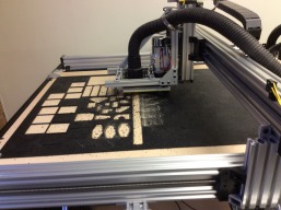
After that, I finished up the clamping and dust collection system and was able to make a first cut before I had to end for the night. The clamping still needs a bit of tweaking since the square I cut out slipped a bit and so one side is not true.
The main workpiece is clamped on either side by a pair of beams clamped down at either end. For pieces being cut out, I am using a modified pressure foot mechanism to keep them clamped during cutout.
The modification is a pancake sandwich which lets me attach a dust collector hose to use alongside the pressure foot. This will (assuming I get the above bug worked out) allow me to use dust collection when cutting out small pieces without having to use tabs.
The top piece has holes for the vacuum tube and spindle. The middle pieces have a hollow connecting the tube hole to the spindle hole. While the bottom pieces do not have a vacuum hole and act as a kind of skirt.
This really only works when you have a known thickness stock (1/8" thick in my case) and you aren't planning on doing any relieve or other large pocketing. But it should let me quickly and easily make ABS plates of any design quickly and with a minimal of setup and cleanup.
The sandwich is held onto the gantry plate by a makeshift skeleton of extrusion pieces. To change tools, I have to remove the whole dust shoe assembly first. I also need to remove the dust shoe to do a z-touch probe. So I only z-touch once to probe the spoilboard surface. Then all my g-code is based on the spoilboard surface instead of the surface of the stock. Having homing switches means I can store that z-coordinate as a working origin in between jobs.

After leveling the spoilboard, calibrating the machine, and figuring out the clamping system, the Contrariwise router is now in production mode making plastic parts.
I discuss some of my troubles in calibration and the solutions here: Debugging Oversized Part

The idea is to only use large solid pieces of 2'x4' plastic. I first cut out pieces on one end, flip it around, then cut them out of the other end. This means that I can clamp the entire edge where the extra size hangs off the edge with a board and a couple of C-clamps. The X gantry can never get to that part of the router, so I don't need to worry about clearance.

Next to the board I've screwed in a couple of plastic pieces to act as a side guide for the sheet of plastic. This way I can position every plastic sheet consistently. The spindle will get nowhere near these screw heads, which is important.

When I leveled the bed, I was a bit worried about the fact that I couldn't level out where the board clamps the plastic to the bed. This means that the plastic there will always be at a slightly higher level than the leveled part of the bed. The solution is to level out a little 'DMZ' here. I've leveled 5 inches or so beyond where I will be cutting. And that means that even if I re-level the bed quite a bit, there will always be a reasonable ramp down so that I'm not warping the plastic when I cut.

At the other end, I use two L-plates to clamp the corners. I need to keep the spindle at least a few inches from the corners, but this still leaves me with almost the entire 2' x 2' area free for cutting. The pressure foot with stronger springs does a great job of keeping the small parts in place as I cut them free, so I don't need to worry about any other workholding.
I talk a bit about how I use the pressure foot and my experience with it so far here:
Dust Boot and Holddown in one
Eventually, I'll set up a whole plate full of parts at a time and cut them all out. For now, I'm cutting one or two parts out at a time while I experiment. The easy way of doing this without accidentally using space that was previously used is to drag each part into a single file. Only save toolpaths for new parts to gcode for actual cutting, but leave all the old shapes in place to show you where you've already cut.
The prototyping loop seems very short with this method. There is no need to re-clamp, re-measure, re-zero or wait half an hour to 3d print a plate and hope it doesn't warp. If you leave everything running, all you need to do is import the part design into the CAM program, generate g-code, and wait about a minute for the part to be cut out. Dust off the part and it is ready to use.
Contrariwise -- A C-Beam Router
Build in 'Cartesian Style CNC' published by Jonathon Duerig, Jun 22, 2016.
A C-Beam router made almost entirely of standard parts. Electronics include an xPro v2 board and NEMA 23 motors. Cuts are made with a small 300W DC spindle. A pressure foot is used to minimize the need for workholding.
-
-
Build Author Jonathon Duerig, Find all builds by Jonathon Duerig
-
- Loading...
-
Build Details
- Build License:
-
- CC - Attribution - CC BY
Reason for this Build
I need to cut a lot of ABS pieces out of sheets.Inspired by
OX, Shapeoko, C-Beam Linear Actuator
![[IMG]](proxy.php?image=http%3A%2F%2Fopenbuilds.com%2Fdata%2Fattachments%2F16%2F16449-8c942da11655305f1d1a46568ca67478.jpg&hash=623e3ce151d8f45cdc3ac25757c54ab5)
![[IMG]](proxy.php?image=http%3A%2F%2Fopenbuilds.com%2Fdata%2Fattachments%2F16%2F16450-c08b6b0cb667db0607a725f04eaaeeb3.jpg&hash=38822f6cf36a5d8d99e31f26927442bf)
![[IMG]](proxy.php?image=http%3A%2F%2Fopenbuilds.com%2Fdata%2Fattachments%2F16%2F16465-1338e207dfaa6002daab2d85d1788382.jpg&hash=491c89cadfb6d42ddac8cae010f97f8f)
![[IMG]](proxy.php?image=http%3A%2F%2Fopenbuilds.com%2Fdata%2Fattachments%2F16%2F16466-f7792829bd540edd61fcb6f25c81d15f.jpg&hash=713f2a223dd69553699f513cdb1a0bb2)
![[IMG]](proxy.php?image=http%3A%2F%2Fopenbuilds.com%2Fdata%2Fattachments%2F16%2F16467-a58a08d255923ec0abde75524d20cf59.jpg&hash=612f22ed3b26ebfd7479ccdac1ba05f4)
![[IMG]](proxy.php?image=http%3A%2F%2Fopenbuilds.com%2Fdata%2Fattachments%2F16%2F16516-0017d598e956d42cae1996317d9e216f.jpg&hash=ed168baf8f434e16bc199427ba7b0225)
![[IMG]](proxy.php?image=http%3A%2F%2Fopenbuilds.com%2Fdata%2Fattachments%2F16%2F16517-70c02fa9cfcd3d655fa6fb34e10f32dc.jpg&hash=c415a85255854eda3859c20f54c93c0c)
![[IMG]](proxy.php?image=http%3A%2F%2Fopenbuilds.com%2Fdata%2Fattachments%2F16%2F16518-64be021e9cf0f196471058859e72ca47.jpg&hash=a04fd1674e095babfdb205a2ebc1a9a4)
![[IMG]](proxy.php?image=http%3A%2F%2Fopenbuilds.com%2Fdata%2Fattachments%2F16%2F16519-1ee9c7f62f7014f17435c3046a02d062.jpg&hash=fdb405ceb35c7809d894cf18ea98dc64)
![[IMG]](proxy.php?image=http%3A%2F%2Fopenbuilds.com%2Fdata%2Fattachments%2F16%2F16521-6aa4ecdef99ed99a4ce5c9e997a2b648.jpg&hash=bf18d88aadf9f7fa0003de95711046c6)
![[IMG]](proxy.php?image=http%3A%2F%2Fopenbuilds.com%2Fdata%2Fattachments%2F16%2F16583-2f98dc5f6ae6b1aca7f0be74e0284535.jpg&hash=e20a17f4071d7bb90169c3c5c448976a)
![[IMG]](proxy.php?image=http%3A%2F%2Fopenbuilds.com%2Fdata%2Fattachments%2F16%2F16584-dd906f769d487371a07d4fbe14d59fcb.jpg&hash=2e056d969abb8a9de69be6a6f242314f)
![[IMG]](proxy.php?image=http%3A%2F%2Fopenbuilds.com%2Fdata%2Fattachments%2F16%2F16585-e2d87f1bc5176242e1cc9512f6a5c1a8.jpg&hash=8af127b124b236b145e56c14cc34d66c)
![[IMG]](proxy.php?image=http%3A%2F%2Fopenbuilds.com%2Fdata%2Fattachments%2F16%2F16586-aa78d8782ccb684d278dd8d147e605cd.jpg&hash=6fda0f05ec5c229a474b28e5bbb4297c)
![[IMG]](proxy.php?image=http%3A%2F%2Fopenbuilds.com%2Fdata%2Fattachments%2F16%2F16587-6ac52bad369bdfe97adb72fd5169edc1.jpg&hash=9b29f6f8406c7f193ccaccfd65d7f43a)
![[IMG]](proxy.php?image=http%3A%2F%2Fopenbuilds.com%2Fdata%2Fattachments%2F16%2F16588-f09c237e4a970ca0462d975e1a29633e.jpg&hash=dcf6d5141f754aaf9e265d476a0441b5)
![[IMG]](proxy.php?image=http%3A%2F%2Fopenbuilds.com%2Fdata%2Fattachments%2F16%2F16589-8d7035a5ce48ef25110e792bee8ac8e6.jpg&hash=717f77732248ddfb8dfc4601b3c20a61)
![[IMG]](proxy.php?image=http%3A%2F%2Fopenbuilds.com%2Fdata%2Fattachments%2F16%2F16590-d4dc4e04d8db9c527d3c11bccc1363d7.jpg&hash=9bc75bc316b74d41a4a8f3eb71ff852d)
![[IMG]](proxy.php?image=http%3A%2F%2Fopenbuilds.com%2Fdata%2Fattachments%2F16%2F16610-63bb059686eda85cacbc3009f817be85.jpg&hash=0ca732d26aaf7a8ad02af2f23f423484)
![[IMG]](proxy.php?image=http%3A%2F%2Fopenbuilds.com%2Fdata%2Fattachments%2F16%2F16611-ec9fbeb81fda20f64e3200f02d8f0783.jpg&hash=5c2ca8e903caea00b9a8b67e0e20feef)
![[IMG]](proxy.php?image=http%3A%2F%2Fopenbuilds.com%2Fdata%2Fattachments%2F16%2F16612-8a653f8310fa33a126eb2d0dfb668fa1.jpg&hash=60f2571482d58735621d5c4bb2809229)
![[IMG]](proxy.php?image=http%3A%2F%2Fopenbuilds.com%2Fdata%2Fattachments%2F16%2F16613-259bda19fa02999047985195b9ca4209.jpg&hash=42c1bba2c0b79e76459d97138310dc9e)
![[IMG]](proxy.php?image=http%3A%2F%2Fopenbuilds.com%2Fdata%2Fattachments%2F16%2F16614-bb51efad73586840f818909ec54c177f.jpg&hash=f355fb7e67ea234e7905ecff23086819)
![[IMG]](proxy.php?image=http%3A%2F%2Fopenbuilds.com%2Fdata%2Fattachments%2F16%2F16615-88922372ebd3a7a66924da4e1df5abf4.jpg&hash=aca864adcf873a0123130bc78b5e761b)
![[IMG]](proxy.php?image=http%3A%2F%2Fopenbuilds.com%2Fdata%2Fattachments%2F16%2F16616-e3e143f4cb83494b93448c9eeb3fd70c.jpg&hash=44748365790311ed2c2b028a5cfd31ff)


