
History
I've wanted to build my own CNC router for a long time now. But I had one major problem. For a router to be useful for my projects, I want a 120cm cut area. However, that would mean a 150x150cm "storage space" requirement. Which would take a large chunk out of my garage. And it wouldn't see daily use.
Then I saw the Crawlbot | Printrbot which could be stored away, and still cut a large area.
So I set out to design that (as I couldn't order it. Too expensive and no shipping option to my country) while designing it I discovered that a full-on crawl bot was difficult, due to the X alignment being depended on the side of the table, and requiring a lot of spring loaded wheels because of that.
However, I still like the low storage space requirements. So I came up with the hybrid design that I'm building right now. The LimpyCNC.
Goals
The goals of my CNC are:
- Large cut area (at least 120x120cm)
- Cutting plate materials of wood
- Low cost
- Accuracy not to critical (0.5mm would already be fine)
LimpyCNC
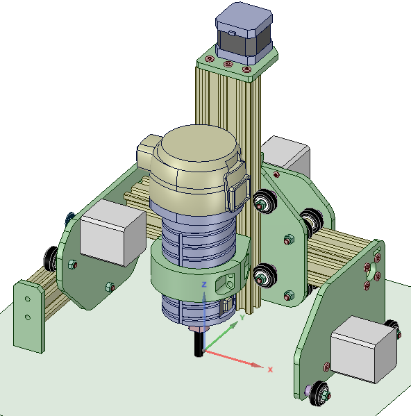
This is the current LimpyCNC v0.11 in CAD. I only drawn the X/Y axis as 250mm instead of 1500mm to keep the overview easier. I also flipped around the right side during assembly, or else it didn't fit in the space reserved due to my lathe.
The CAD drawing lacks belts.
The build
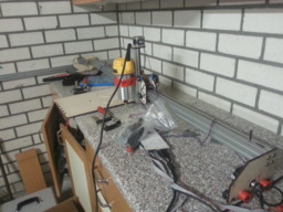
I've assembled LimpyCNC v0.1. And made the first cut.
As a picture is a 1000 words, here are a few blurry photos (sorry, don't have a quality camera)


I'm using a Dewalt D26200 (DWP611 for US people). The mount is a 3D printed bracket, as well as 2 idles on the right side. The motors are beefy NEMA17 motors with 400 steps per rotation, Ultimaker 2 feeder motors to be exact. All the belts are GT2. The wooden parts are 6mm ply. The electronics are Ultimaker 2 3D printer electronics. Z spindle is an Ultimaker 2 Z spindle cut to size.
The plywood parts where cut on a Speedy 600 laser cutter, which I have access to in our office. Most of the parts come from Vslot Europe
The red idlers where 3D printed because I forgot to order some, and I figured I could just print those. There are bearings inside the prints (put in during printing). There are no idles on the rest of the parts, as the wheels double as idles for those. So I only needed 2.
I had to flip around the right side assembly compared to the drawing, or else it wouldn't fit on the deskt next to the lathe. In the drawing this is the other way around to get a few cm of extra movement room. But I figured I don't really need those few cm. And the lathe is a bit heavy to move off my desk, even if I'm not really using it.
Wiring is still a mess, so that needs to be fixed before I can move the full area. And the belts are only 1000mm instead of the full 1500mm. (Proper belts didn't arrive in time, and I had some spare stuff from Ultimaker, I hope you see the pattern by now)
Software
Well, for control software, I've made my own, based on Ultimaker 2 firmware, and thus based on Marlin 3D printer firmware. Pretty much stripped it down to the bare and rebuilding from there. Guess what, I'm a software engineer by trade. This stuff is what I do.
Don't have CAM software yet... but some people might recognize my nickname. If you are in to 3D printing, Cura was my "brainchild". So I can handle that part in the future.
The circle was cut by programming the motion directly into the control software.
The problems
No version 0.1 build is without issues. So this build has issues. As not exactly clear from the photos, that circle isn't exactly round. There is quite some flex in the ply that the Z motion is attached too. The wheels that clamp the X carriage are also not tight enough, and the adjustment nuts are at the bottom, so I can no longer reach those... so got a few things to change for v0.2.
v0.11 as seen in the drawing above has a few tiny fixes compared to the build version. Mostly holes for cable and belt management. Wasn't worth re-cutting the parts just to get those changes.
So, I'm heading back to CAD now to fix those things. And most likely will cut things from aluminium once I got the drawings proper of the X carriage plates.
(Can share design files/drawings on request. But as this version has flaws. It's not wise to build it)
LimpyCNC
Build in 'Cartesian Style CNC' published by Daid, Jul 25, 2018.
Inpired by the OpenBuilds OX and PrintrBot Crawlbot. This is the LimpyCNC. It's still a work-in-progress. But it provides a 120x120cm work space without using up 150x150cm of garage space.
-
-
Build Author Daid, Find all builds by Daid
-
- Loading...
-
Build Details
- Build License:
-
- CC - Attribution - CC BY
Inspired by
OX, Crawlbot