
I have a sign in my workshop that states "If you can imagine it, you can create it", That is my approach to life.
Before I start my build I had to think what I want out of a machine and what size `I expect to make when using it. I am anticipating to make items a max 300 to 400mm square in wood or aluminium.
What are the options?
1. A pre-made Chinese machine of doubtful quality that can only be driven from a computer parallel port.
2. An OX kit by Openbulds larger than I need unless I redesign it.
3. A C-beam kit by Openbuilds smaller than I want unless I redesign it.
4. I design my own machine that meets my requirements.
Where do I start? With the frame or the electronics? Am I putting the horse before the cart or vice versa? I think I will put the horse in the cart and pull the cart instead. I am going to start with the electronics as no doubt I am going to hit problems and may take time to resolve.
I have the following items ready to start the build:
24V regulated power supply
CNC USB Controller/Breakout board - I am not happy with a parallel port controller
3 TB6560 stepper drivers
Spindle motor speed controller.
3 Nema 23 motors 1.26Nm(178.5oz.in)
400W spindle mount motor and speed controller
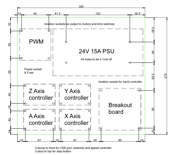
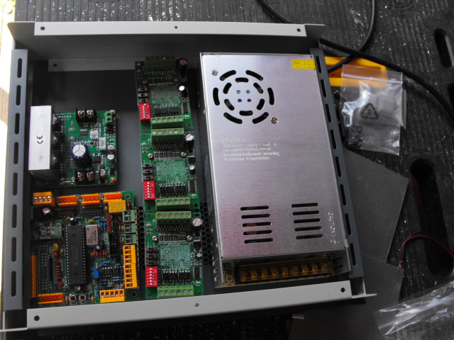
I am looking for a case to hold the items so my first task is to set the items out for ease of access and adequate cooling. This gives me a case size of 279x305x65mm.
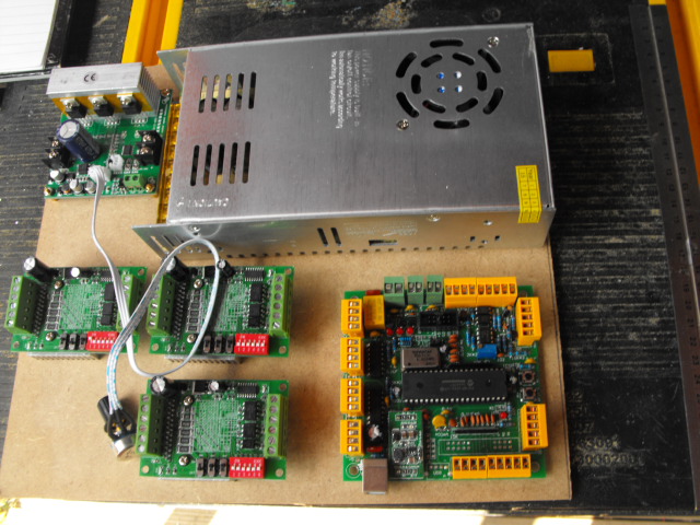
I have laid out the boards on a piece of MDF cut to size to assess clearances for cables and it leaves space for a 4th stepper driver.
I am going to start by fixing the Breakout board, power supply and one stepper driver to see if it will work. If it goes bang not too much is lost! The stepper motor - I will be using a cheap Nema17 motor instead of the Nema23's on the planned machine, will be driven using the jog mode on the breakout board.
The breakout board appears to be a clone of a Planet-CNC board and came without any instructions - so watch this space!
The case layout is finished and the case ordered - just in time for the weekend!
Having a Nema 17 stepper motor that I could afford to lose should things go awry, I had to search for the correct linking circuits on the Internet, I must thank Electrodragon for the necessary information on their website. TB6560 3A Stepper Motor Driver Board Single-Axis - ElectroDragon
I made the connections to the A axis on the breakout board.
5V supply was provided by my battery adaptor and I used a length of wire to make contact with the A+ and A- jog terminals to control direction of the motor. With bated breath, I powered up and - the LEDs glowed. So far so good, lets see if the motor turns.
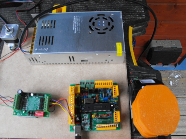
SUCCESS - after a couple of hours, I have just connected the boards to a Nema17 motor and used the jog connections to make it run clockwise and anticlockwise. It spins too fast and my next purchase will be a 50ohm rheostat to control the jog speed. I will reset the board and try with a Nema23 that will be used on the final build.
I have started to connect the wires for the remote control and preparing a design for the hand held unit that will be printed with my 3D printer although it will only be a 3 axis version.
This is now on hold until the case arrives and is populated.
I have nearly finished construction of my trial rig to test the electronics and software as well as to see what flaws need to be resolved in the final build. I have used 2040 sections cut to suit and it will be driven with Nema 17 motors. All the carriages have been printed with a build cost of about £35 + motors.
The plate size is 250x250mm and the work area is 200x160mm and could be upgraded for use as a pcb engraver.
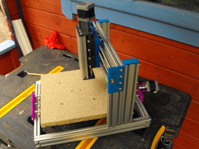
The problems so far:
Excessive deflection of the Y axis - to be resolved by adding additional rails and wheel kits
Difficult to manually wind the threaded rods - to be resolved by lengthening them and adding a knob.
Robustness of the frame itself - gussets to be resolved after testing
The case arrived - better late than never. Horror, the case is a mirror Tardis - smaller on the inside than the outside!! I enjoy a challenge, the clear dimensions inside the case are 273x235, so there will be some replanning of the layout. It will fit, tight perhaps, but it will fit.
I have just started to fix the panels inside the case - so far so good.

My First CNC Machine
Build in 'Other Style CNC Mills' published by andy-may, Jun 2, 2016.
This will be a step by step record charting my successes and failures in my voyage of discovery while building a CNC router. Please excuse my English-English which may lose something in translation to American-English. I would be grateful for any advice during the build
-
-
Build Author andy-may, Find all builds by andy-may
-
- Loading...
-
Build Details
- Build License:
-
- CC - Attribution NonCommercial - Share Alike - CC BY NC SA
Reason for this Build
I enjoy a challenge and want what I want. The finished machine will be used to engrave and cut assorted materials up to 300mm X 300mm.Inspired by
My Imagination
