
[Revised 2016-03-14 - see bottom]
This is my adventure with an OX build and the V-slot system. Grab a cup of coffee and enjoy (at least the coffee) ...
It all started with some innocent surfing of the web. Goes to show what sort of trouble one can get into surfing the web ! Here I am building a CNC router / milling machine with NO previous experience, no particular skills or knowledge. Sure, my dad was a machinist/tool and die maker since for ever. Some of it might of rubbed off on me ? But that is as close as I ever was to being mechanically inclined. Mind you, in the last decade or so I am amazing myself (and others !) But enough about me, on to myOX we go ...
After much surfing, looking for ... I forget ... something better than surfing the web ... I happened unto the OX CNC build, OpenBuilds and related forums purely by accident. Many many hours later, looking through alternatives, including... turn away... pre-built multi thousand dollars machines - all way way off any of our budgets, especially mine, I was "sold" on all of the merits of the OX design. It's certainly a change from my usual interests.
One can follow Mark Carew's detailed OpenBuilds OX build (the videos are very good guides), any of the growing number of variations found at OpenBuilds, like this one ... or let their imagination go for their dream machine - that "perfect" design. I, being who I am, chose the latter route. Thus began my adventure building myOX.
Once I decided on the base design, I began dreaming about the "perfect" enhancements ... Dreaming, as I perceive it, is the easiest part of the project. So might as well go for broke.
Thinking about it I will probably not do much for a while with myOX, but I do like to think way ahead of myself. So I wanted a machine which could basically mill a complete door panel or conference table top ! While a reasonable budget was about the only limit. So I grabbed SketchUp, took the base design of the OX and I started modifying. Never quite getting there... at least on the screen, too eager to have parts in my hands. Even now, months later, the file is far from done as it remains untouched. But one will follow, eventually.
The catch was the size of my garage (technically called a "1.5 car garage"... if you drive a Smart) and my wife's car, much bigger than a Smart, occupying the space most of the year. So I started scaling myOX down a bit, realizing I might just do the odd cabinet door, maybe the odd sign or two and ... a few mold bucks and parts of some kind for my other recent hobbies, namely scale R/C monster truck, plane and multicopters. IF I ever can trust myself in pointing myOX's tool end to my gagdets, maybe some fancy precision engraving to make them mine. Anyone engraved their name on their iPad or such ?
Oh, very important here, I also wanted to keep the cutting of V-slot - or anything for that matter, to a minimum.
(2014-11-11) As it turns out, after months of head scratching, this goal was futile. You MUST measure every single lengths of V-slot, whether you cut them or not. Extruders go by a standard tolerance to cut extrusion. It is about +3.25 mm / -0 mm, depending on the source. Of course, you can get a very precise cut (0.01 mm or 0.0005"). However, you will have to pay for the precision out of the factory. So my "uncut" lengths of V-slot, the most critical being the three used for the X beam, were off. This caused a substantial error along my X axis. An error I could not figure out ...
You'll need to MEASURE at least twice and CUT all of your lengths to what you want !
myOX became a 1500 mm wide (X axis) by 750 mm deep (Y axis) with a Z axis of about 10". This is a good 4' x 2' of working area. With the 4+' width, call it the throat, I could, one day, route / mill plenty of projects ... as long as I do it in sections of about 2'. Just slide the work piece between sections. The approach sounds reasonable enough, for now. I will figure the part about aligning sections when time comes to work such a project. No rush at this point in time.
[2014-11-11] Work area is more like 52" wide (X) by 19" (Y), once everything is said and done. There's a 9.25" or so deadzone in the back - distance from centre of bit/tool when myOX is all the way back... A overhang also exists as the tool centre reaches passed the front of the base (!) To keep the tool within the base frame, there is a bit more than 19" working Y range. The overhang - working above the base, adds about an 1",
With its Z-axis and a "plan" for myOX to become "bottomless" (or is it the table being "topless" ?), at least for a fair sized section of its work area, I could work on projects needing to go deeper than most would expect. In fact, the plan goes a step further with the eventual addition of a 4th axis "beneath" myOX. It can be manual initially, no need for a fancy 4th axis, at least for now. Think of working on the 5 faces of a mold buck - a cube, or more of a parallelepiped, for a scale truck body (bottom's flat) without a fancy (and expensive) 5 axis milling machine. Just rotate the work piece 90o to change the face worked on, align some reference point and mill/route. Repeat for other faces.
Now (which was back in June 2014) armed with a concept and its evolution for the next little while, I went off shopping for the various components. My bill of material became, more recently, OXCalculator - the resource available on OpenBuilds. Give it at least three basic number and it generates "your" bill of material (BoM), budget planner and, eventually, shopping list.
I, like most others, had to hunt for the many parts including the sometimes quite elusive V-slot. The next lesson came hard : have an updated and verified parts list specific to YOUR design ! It seems as obvious a step as any other, but even the standard OX parts list has a few ... let's say ... discrepancies.
OpenBuilds PartStore, OpenSource Luthier Supply, ProtoDrake (in Canada, like me), StepperOnLine, McMaster-Carr, Fastenal (on Canadian side for me) and even unlikely sources such as BangGood, the local Canada Salvage and Canadian Tire stores came into play as the build became more precise and I started ordering some extras and even blings to dress up the yet to be finished myOX.
As of June 19, 2014, the mechanical assembly was just about done... short of the spacer length to hold the work surface as I am short of ... ya ... T-nuts. It's always the lowest cost part which will be holding up a project. Turns out my parts list, before having the OXcalculator, was short on a few items. I will blame my dyslexia for some of the errors, like ordering M3 screws instead of M5. Just being in a rush to get started actually slowed things down... For now, this remains a weekend project, having a more than full time job ... and a (wonderful) wife.
Mind you, all of the electronics was actually in at that point. Well, at least the initial thought : Arduino plus a shield and drivers. Waiting for the missing parts, I was figuring how to wire everything neatly.
[2014-11-12] The few weeks of waiting for parts to arrive is a good time to start learning the software end of your build. A thing I unfortunately didn't really do. So myOX is now waiting for me to catch up !! I can work my way through SketchUp, but I still have to figure a good way to end up with the Gcode file. SketchUcam seems a good starting point. Of course, there are plenty alternatives, from free or almost free to ... expensive. The latter will be for when I get to use myOX and its offsprings on a regular basis, if even needed.
Along came an other KickStarter of particular interest : CNC xPro controller. A very interesting "all in one" Arduino controller with drivers, etc. on a single board. It is perfect for at least the beginners - ie : me ! The pros can also benefit from its ready to run configuration. I took it out of the box, plugged the things in and within seconds could hear my steppers stepping. This was much easier than with regular Arduino plus shield plus drivers plus loading software ...
By October 2, 2014, myOX was virtually done ... or so I thought at the time ! It should of needed some fine tuning of GRBL parameters - namely adjusting steps to true scale. Do not forget, the ACME screw from OBPS is a 4 starts, that's an extra division the online calculators I looked at didn't make clear...
It was time for some pictures. The backstage pictures can be found in this post as myOX takes shape.
On the mechanical side, I came up with a few tweaks, some due to getting regular head M5 screws - required a few extra shims here and there, others just because I tend to be "lazy" (in a good way)- a quick and dirty, not that type of dirty, jig allowed for assembling the X/Z assembly in no time flat... But since then I had to take it apart a few time, including a few times as I though myOX was nearly complete ...
As with any other design one can customize, there is always room for some improvements. So be on ready for taking a few steps back from time to time. You will even reach a point where your OX will make parts for itself or a few offsprings.
At times I thought I was going to end up with a FrankenOX. But the dressing up of cabling, along with some custom plexiglass bending/shaping, is giving myOX a nicer look as it sits on its very own custom made workbench. There's pictures of all that along the way in the posts (see previous link). Anyways, follow the discussion threads down below for more on the myOX saga as it unfolds ...
October 8, late night, and myOX is drawing on its own ! I almost felt like pulling out cigars. Then, I realized I don't smoke nor have any cigars. Still, it was a proud moment to remember. Time for the YouTubing to start ...
But that was only the beginning of the fun. myOX was ... cross-eyed (divergent at that !!)
Because I didn't measure the pre-cut lengths, as of October 14 I have no choice but to take myOX to pieces and CUT the three 20x60 lengths to equal size. In theory, I should be able to trim them down towards 1500 mm since they are all nearly 4 or so mm longer. How can I do precision cuts ?
The old chop saw used to build the fence proved on a small piece of V-slot that it was not up to task ! Back to the internet I went, checking for a good miter saw which wouldn't double the cost of myOX...
Time passed and my attention went for the Evolution Rage 3 multi-purpose sliding bevel miter saw - a miter saw with loads of potential in anyone's tool shed. I could not ignore fact it was also on special at the local Canadian Tire - 300$. Thus quickly available and within my "budget" for a tool I was actually borrowing much too often from others. At worse, it would be my miter saw ... and I would not be able to do the precision cut needed... As it turned out, an adventure of its own, the Rage 3 CAN do the job. It just takes time to properly square blade, table and fence... From there, it cuts through the extrusion like 'butter'. The trick, thanks to some advice received here in OpenBuild, is to do a "shaving" motion - bring the blade up & down a few times to make certain there is no blade defection at work against you. I'll let you read the various posts and do your own research. It is an excellent all purpose miter saw. I already used it for a few other unrelated projects - cutting through aluminum and steel with no issue. Cutting wood is a dream. I wish I had this saw back when doing the deck and fencing ...
So here we are, Novembre 11, 2014 and myOX looks pretty darn near done with a first few test routing showing great improvement in its precision. Given the width and basic design, I don't think an OX this size - with a 52" x 20" working area (plus down to about 20" depth in Z), will get to 0.01 mm precision. But it looks like it will do all I am planning to date.
Let me do a few videos, get myOX to redo its own 'precision milled' Y shield (out of plexiglass ... details to follow as a new ressource), a few sliding limit/home switch holders and the odd "test" projects... The wife has a few Christmas gift ideas for me to try. So time is running out ...
[Revised 2014-11-24 - got busy the last couple of weeks with health issues and work]
I did a few small test cuts, just to see if precision was not too bad. It seem pretty good since the last tweaks.
Find in the post the very latest "real" cut. It's an 80x80 fan shield taken from an STL meant to be 3D printed ... My job run ran into an issue I have to figure out before going into 'production'.
[Revised 2014-11-27]
Ok, what is going on ? The Y stepper closest to the controller seems to be acting up. I ran a test piece "fleur de Lys" (curves and larger than the 80x80 fan grill). Was a bit agressive with the cut depth and could see some strain ... but tool pathes were consistant. So I tried the fan grill again, and this time it was completely messed up ! I'll have to check that stepper and the wiring ... but I'll regenerate gcode files as well since I played with meshCAM way too long the other night (not saving the original output file).
Now using the UniversalGcodeSender-v1.0.7 instead of the GRBLcontroller, still running off the olde MacBook. Can see more status info on what is going on, better manual control, ... just plain nicer. It could use the large "readout" instead of plain text.
Getting that much closer, if I could only figure out what is going with my Y steppers. I might need to feed more current to them. They are running quite cool (NEMA 23) compared to the warm Z (Nema 17). The X stepper (NEMA 23) is also running cool.
[Revised 2014-12-01]
Well, the hunt for a 24+V power supply ended with an order direct from China. It will be 20$ or so, delivered to my front door about two weeks from now. All of the other options were triple the cost. I'll just have to be patient for another couple of weeks.
[Revised 2014-12-21]
Those having read the long posts, will know about my power supply adventure. The 24V didn't do much helping. At least not with the problem I had. Thanks to John, I was set on the right track ...
First off, make sure you have your GRBL settings tuned halfway descent ! I had a few settings way off. Critical, beyond the steps per mm, are the step pulse and idle (depends on the driver chips) as well as the acceleration, feed and seek rates (speeds). All of these keep your steppers run smoothly (less 'chatter', etc.)
Then make certain the driver's current is appropriate for your steppers. The CNC xPro lets you set this for each driver/motor. Although you have to eye ball it (would be nice to have a read out ... for us beginners at least).
But the most critical, especially in the mystery regarding myOX misbehaving, was the temperature reached by the driver chips. I must admitI had the heat sinks and three fans in their bags - not installed ! Once the heat sinks stuck to the chips ... miracle of miracles ! ... myOX behaved like any good OX should. Perfect runs, no stalls ... just routing nice and fast.
So, once again, it was the "5 cents" part which made (rather broke) the entire system ! Or, more to the point, the oversight on my part not to stick to the plan of installing the heatsink from day one !!
At this point, myOX is nearing 'completed'. However, the build will go on as myOX will cut new set of plexiglass shields (with space for buttons, fans, etc.), limit switch sliding mounts, etc. In fact, I'll have a few other builds/ressources rolling out from here on ...
It will be a Merry Christmas and a Happy New Year indeed ...
[Revised 2014-12-22]
myOX is doing well as can be seen from a couple of post of YouTube clips : a borrowed test signature and a Fleur de Lys (also my very first Meshcam conversion of a black and white image to g-code !)
Knowing myself, the build will never be quite "complete" as I will find little (and big) things to tweak as I use myOX for practical (and not so practical) projects. Nonetheless, I think myOX is at a stage I can check the "completed" box since it can go through more than one job.
Keep coming to this project and others as it will continue to evolve and have offsprings.
Aspects remaining to be done, in no particular order :
foreseeable offsprings :
- redesign the dust shields (Y gantry plate guards) with vents, fans, buttons, etc.
- add lights and other blings, not forgetting a camera mounts to show off !
- design sliding limit/home switches and stops (I'll need these before too long !)
- add a dust/chip collection/vacuum system (working with MDF sure makes a mess !)
- redesign work surface for part clamping and maybe even add a vacuum top
- opening the workbench top as much as possible
- design a workpiece "slider" for anything longer than 19" which fits the 52" throat !
- design 4th axis (manual at first) to work at least four faces (0, 90, 180 and 270) individually
- swappable tool/head - got the laser on its way already ...
- redesign the whole thing for "deep" Z (needs to be very stable/sturdy to keep precision)
- ...
Thanks one and all who helped along the way and, most important, put up with my learning curve ... The bad news for you, I'm just getting started !
- a smaller transportable miniOX (something to bring along and to do small jobs)
- maybe a microOX just to see how small I can go (random parts already on their way)
- something I would initially call a stOXer - I still have to think about that one
- a walking and maybe even 'climbing' spidOX - how precise and useful can that be ?
- still thinking about the poleOX - I just have to see if it can be done (by me at least)
- ...
[Revised 2014-12-30]
Oh ho, and it ain't Santa Claus
Running several jobs since the last news, experimenting with software and getting used to myOX. I'm running into a few more issues. Check out the post(s) for details ...
.
[Revised 2015-02-20]
With most of the updates done within the discussions, here is an overview :
> darn temperature is way too cold to work in the garage, even for a Canadian, reaching towards -40 (C or F gets to be just as cold at that point). The garage is not a place to spend hours ... even with an OX.
> the powered heavy router still creates enough vibration to see the Z slowly slide downward.All things considered, myOX is working much better than its owner/operator.
> bungee cord trick definitely has its limits : if you want to move Z more than 1/2" or so, the bungee will actually bounce the router way too much upward !!! So this trick is only good if you do real shallow work.> squaring your OX must include the work surface, especially if you have a wide OX. Mine was a tad less than 2 mm off from X = 0 mm to X = 1500mm, which is nearly 5/64" !!! Ya, that's what my did would of called a fat 1/16", visible even with my beagle eyes. A huge difference especially IF you are doing anything but cutting through material. A .07" error is not what even I could call high precision when doing pockets and such. On the other hand, Y and Z seem quick good.
> best to set idle delay to 255 and keep the steppers powered all the time : that did the trick ! However my Z stepper, a NEMA 17, gets real hot, even in the cold garage. I need to tune the amps down. There has to be an easy way to get this done then guessing the pot position ...
> making the spoil board square with your tool end, especially if MDF, makes for a lot of very fine dust ! I do mean A LOT of dust, especially when it settles down. So don't forget to take the wife's car out of the garage BEFORE starting that job EVEN if it's -40 outside. How some use their CNC in the bedroom is beyond me at this point ... And get a mask !
> always measure your stock before starting a design or a run. The 10"x24" plexiglass pieces I had bought are actually more like 9" x 23 1/2" ! So optimizing a design for the nominal dimensions IS not the way to go ... Allowing for some waste will also make aligning and clamping material much easier.
Limit switches are nice to avoid going further than what the machine allows when unsupervised... But the odd false triggers will waste material. So either get the proper circuitry to avoid false trigger ... OR admire your machine at work with hand near (big red) Emergency Switch or ready to unplug it all.
Discussions area will always have more ...
[2015-03-08]
Time for a bit of spring cleaning ... before taking off to the warm South for a few days. myOX found its new 'permanent' place in the garage. The wife's car gets lots of room, as most of my 'junk'. Upon return from the South, where temps hit the +30 C (instead of the the -30 C here !) I will tackle some upgrades to myOX and get it into production : dust vacuum & shields, get the family tree routed, ...
Am I not sure which is most existing : the trip South or the return to myOX ?
[2015-07-14]
Time does fly by. Trip down South was great. Work was ... work. Blabla ... Over the last few months (!) I have experimented further with myOx, heading towards some of my original goals : wide & deep.
I can imagine a few "told you so" coming. But, hey, I needed to live the experience. So check out the discussions as the interaction will surely add more than my enlightenment of the last few months.
[2015-07-19]
myOx is fully operational !
After changing the smallish NEMA17 used for the Z axis to a hefty NEMA23, as well as finally adding the fans over the controller, myOx has now ran for over 3+ hours non-stop with not an issue. Each of the steppers are running relatively cool, the controller is holding up its end as the router.
So don't skimp on the steppers and don't forget to keep the controller 'cool' ! Both were my top issue from the get go ...
Now the fun will begin
[2015-09-10]
In between several visits from family and friends, I managed to get a bit of practice with myOX ... Did the one sign and now a very first, ever (for me), inlay ! Check out the post for details and pics.
I can see many more projects done with myOX. I also just received a microwave kiln for glass fusing & slumping ... there could be some nice synergy at some point down the not so long road ahead.
[2016-03-14]
Seems like time flies by faster as one ages ...
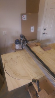
Well, I finally got around to testing the "infinity" mode. If you recall (or read all of the above and the discussion) one of the original intend of myOX was to be able to mill/carve/cut up to at least 48" and as long a work piece as I could somehow clamp through its 20" (Y) by 52" (X) throat.
Check the discusion thread, starting at around March 14th, 2016, maybe a related resource or two as well, to see how I cut a 30" diameter croquignole game. I made a guide to get the aligment just right, etc. Now I need to figure a good way to clamp that big of a work piece so it lays nice and flat ... which could very well be Florian's "Dust Boot and Hold Down in one". Perfect timing, isn't it ?
myOX : a 4' x 2' OX CNC with potential
Build in 'Cartesian Style CNC' published by Serge E., Mar 14, 2016.
This is the story of me building myOX - my version of the "ideal" OX. I want a machine which can route/mill at least 4' wide and as long as I can feed through (don't be shy, think "infinity") as well as going deep on multiple faces - manual 4th axis. I have loads of ideas to take myOX towards that goal and way beyond. Time will tell. Just follow along through this build and possibly a few others along the way ... Check out my OXCalculator : let your computer figure out your BoM
-
-
Build Author Serge E., Find all builds by Serge E.
-
- Loading...
-
Build Details
- Build License:
-
- CC - Attribution Share Alike - CC BY SA
Reason for this Build
I sure would like to know ...
It started with my getting into scale R/C monster truck and not wanting to pay a fortune for body shells I'll be destroying. I started building a thermoforming thing realizing I needed to do molds and not wanting to play with plaster of paris ... So here I am building myOX, having spent well over 1000$ and still no mold done - that's in neighborhood of ... 30 body shells ! Should I mention my monster truck is shelved having burnt the dual motor and exploded the transmission during an eventful stunt ?
But myOX will allow me to engrave and even sculpt a complete extra wide door or even a real big table top ... along with a bunch of signs and whatnots. First, a keychain or something manageable by me more than myOX.
... I guess it was for the challenge as I am not mechanically inclined and needed to challenge more than my overactive single grey cell. Let's get physical ... do some chips, lots of noise late at night and probably more dust than I should !
Inspired by
The one and only OX CNC Machine by Mark Carew and those who followed in his foot steps, as I am doing with the build of myOX -
Parts list
Qty Part Name Part Link Comments 0 Use my OXCalculator ... you'll have your own BoM. http://www.openbuilds.com/resources/oxcalculator-bill-of-... Link Let your computer figure out your bill of material, estimate cost and eventually help you with some decision making as well as give you a shopping list. 0 Link

