2018-07-11
Most of the electronics has arrived and I've spent some time hooking it up for testing.

For the controller I went with a UC300ETH-5LPT, an ethernet connected controller made by CNCdrive, based in Hungary.
That controller is probably "slightly" overkill for my needs with it's 6-axis capability and 49 digital +2 analog inputs and 36 digital +2 analog outputs and obviously more expensive then just using a breakout board connected directly to a parallel port.
Honestly though I don't think it's really that expensive to begin with at ~€160 (with 27% Hungarian VAT) but still my reasoning to justify the cost is first and foremost to avoid having to use a computer with a parallel port.
I probably do have an old computer with the port, or at least with a motherboard header for one that I could have dug out from a corner or closet somewhere, but I just didn't want to, not even to use dedicated with the CNC. Now instead I can just use my up-to-date laptop or SFF normal PC.
Another way I see it is that with this controller you get the option to use UCCNC instead of Mach 3/4 which is supposed to be just as good or even better and a licence for that is $60 instead of $175-200 for Mach. Factor that in and the controller is starting to look really cheap.

To go with the controller I also picked up a breakout board made by the same company, simply called "UCBB".
It's a fairly new release from them I believe but it's supposed to be pretty nice, has all sorts of fancy things that I barely know what they even are at this point, like "optocouplers" and "Open-drain Mosfet outputs" but mainly it just seems like a nicely layed out board that is clearly marked and easy to connect to the UC300 using ribbon cables.
It also has 24v I/O's which is going to be nice if I decide to use proximity switches later.
It only has two IDC26 ports though so in order to use all five ports on the UC300 you'd need something else, or more then one of these. This is going to be plenty for me though.

The stepper drivers is a set of digital Leadshine DM556 units.
I really kind of struggled choosing drivers but then stumbled across these from a US seller for a good price so I just went for it and they seem to work well.
Being digital I guess they are supposed to run the steppers a little smoother and more quietly then analog drivers and they do seem both smooth and quiet with the testing I've done so far, not sure how much of a selling point that really is though on a cnc router I don't think the steppers is the worst source of noise anyways
They are also programmable with Leadshines "Protuner" software so I also got a cable to be able to do that, probably not really necessary for a simple stepper driver like these, the dip switches would have worked well also I'm sure, but hey the cable was only like $3 and it's fun to play with

To power it all I'm using three different power supplies.
The larger one, a Meanwell LRS-350-24 (it is actually kind of small and thin) is a 24v 14,6a unit that is powering the steppers.
The drivers will take up to 50 volts but it's my understanding you want higher voltage for higher speed and since I got a pretty small machine with rack and pinion I won't need much speed and so 24v should be enough.
Then I also got a second, smaller, 24v supply powering the breakout board. This might not have been necessary and I could just have powered it from the same supply as the steppers but I read somewhere that ideally it should be separate to avoid interference or back-emf or something so I decided to play it safe and just picked one up. Even the semi-nice ones like these Meanwell's aren't really that expensive anyways, I think I payed €30 for it so what the heck right.
Then the last one is a 5v supply for the UC300 controller and this is where I screwed up I guess.
When I bought the controller and the breakout board I just quickly glanced thru the manuals for each and read that the UC300 needs 5v and the UCBB needs 24v so that's what I ordered...but I had missed the part that said the UCBB will also output 5 volts that could be used to power the UC300...oh well it's already mounted and plugged in now so it'll just stay there for now anyway.


Since I had never done anything like this before I took the steppers and cables of the machine for some bench testing and quickly whipped up a really professional setup using an industry standard "piece of old chair wood board" to mount everything on, some diy standoff's from flat bar for the breakout board, complete with some really professional looking diy m3 nuts made from small pieces of aluminium.
Also featuring some steel fixing band, double sided tape and Wago quick-connectors and to top it all off: red / black wires for everything! (Except for the 230v side which is actually proper stuff)
Nah, this is obviously just for testing, really not sure why I even bothered crimping on ferrules... Still a few bits and pieces missing, once I have it all figured out I'll just buy an enclosure for it or build one, right now I'm thinking I'll just use the cnc-machine once it's up and running to help me build something nice.


Like I said I had never done anything like this before but the controller, breakout board and drivers all have nice, well written manuals so it was actually quite easy getting it all to work, and it even did so on the first try!
I'm now at the point where I can move the steppers from inside UCCNC and that's really a quite satisfying thing to do
What I need to do now is hook up and configure the home/limit switches and e-stop before I put it back on the machine so I can start tweaking settings and whatnot. Shouldn't take too long but sadly I won't have time for it because life is going to get in the way for a while now but it's starting to feel like I'm getting close and I can't wait to start making chips!
2018-06-24
It's been a while, but now it's time to get this machine up and running!
I've been waiting for the Apex controller (or Blackbox these days I guess) so the whole build has been on ice. But now I'm tired of waiting and will be using different electronics. Atleast for now, maybe I'll still try that Blackbox later.
I have some electronics on order now and waiting for that to arrive so more on that later.
Spoilboard
One of the things left to do was to make a spoilboard, and I finally got around to doing that.
I made it in Rawcnc's "old style" I guess, because it seems like they are using a different style now, but I quite like this. The idea is to use carriage bolts with two sides ground flat so you can insert them thru the gaps, twist them, and then use clamps and nuts to secure whatever on to there.
This style is easy to make too, I made it using some €7 19 mm MDF shelfs, a tracksaw (because I was doing it indoors and didn't want sawdust everywhere, otherwise a circular saw would have worked fine too), a cordless drill and some really careful measuring.


I just cut the boards up, marked them really carefully and drilled 6 mm thruholes that was then counterbored to 8.5 mm to let the screw heads sit a few millimeters below the surface.


The boards are fastened to the frame with t-nuts and m5 screws.
This is why careful measuring was required and also the 6 instead of 5 mm drill for the m5 screws, it just gave me a little bit of wiggle room since I did it by hand and not with a drill press or anything.
I didn't want to use self-tapping screws straight into the extrusions because I think it will be easier to replace the boards when necessary like this. It just took a bit longer to make and used up a bunch of extra t-nuts, but I think it was worth it and I'm pleased with the result.

CRAPPY pinions!
Another big thing that was left to do was to replace the pinions I had.
They were the correct pinions for the racks and they looked fine and I honestly couldn't see anything wrong with them but they just would NOT mesh well with the racks no matter how much I tried to adjust things. They were very loud, felt really rough and made the whole machine vibrate pretty badly just by moving the axis by hand.
I think this was because they were just really low quality and it seems difficult to actually find good quality pinions of this size.
They all seem to sell the same crappy powdered metal stuff everywhere so I reached out to Janne over at Rawcnc and he sent me some of the nice pinions that they ship with their kits, they are apparently sourced from a Swedish company and ground 4 times or more. BIG thanks for that because these work SO much better.
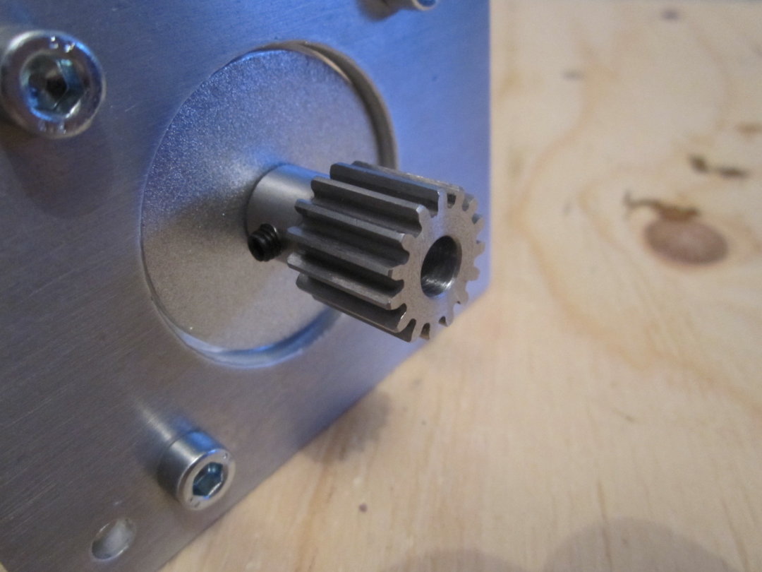
Now I'm not really sure if these are also powdered metal or not, but they look machined to me and they weigh twice as much as the old ones. (22-23 grams instead of 11)

It took just a few minutes to adjust the racks to get these to run nice and smooth without vibrations where I had spent ages trying to get the old ones to work without success. They are still quite loud, but I guess that's just the nature of rack & pinions drives. And they are not as loud as the old ones anyway.
Drag chains and wiring
Rawcnc also sent over some shielded cables for the motors and switches and some nice drag chains.
First thing to do was to solder on the male ends of the aviation plugs to the steppers.

This was a little bit harder then the female ends because they had solder cups and the males just these "pegs".
I'm really not very good at soldering and I'm sure there is a correct way to do this that I don't know about, but I got it done eventually after making a make-shift "jig" to hold the plugs in place.
Might not look super-pretty but they are attached good enough that I couldn't pull them apart again and nothing is shorting so it should work just fine.

The "strain relief clamps" on the plugs was a bit too large for the 20 AWG cables so I put on a few layers of shrink tube. Again might not look pretty, but it works

After doing this to all four steppers I put on the drag chains, just temporarily for now because I'll be taking the steppers off again once I get the electronics so I can do some "bench testing" first since I've never done anything like this before.
The machine is starting to look really good now with the chains on I think!
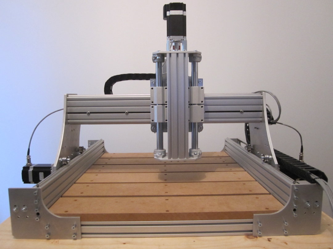


Can't wait for the electronics to arrive now so I can start working on that!
2018-01-08
Finally got around to doing some work on the machine again!
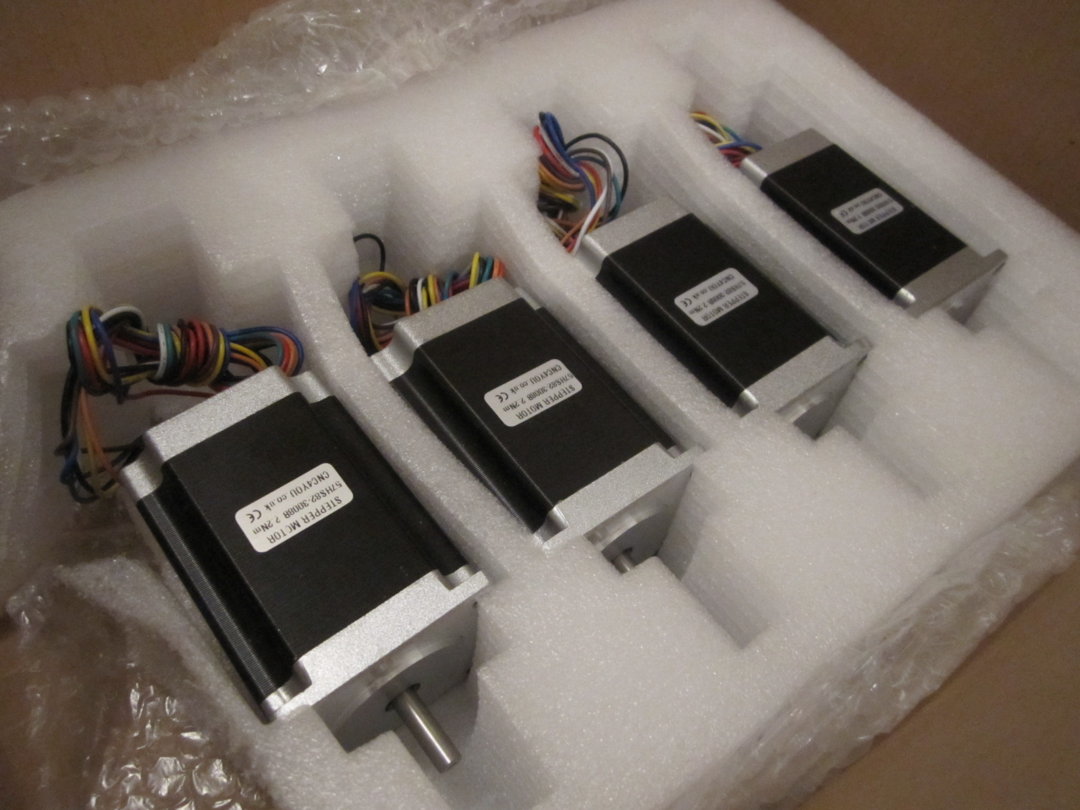
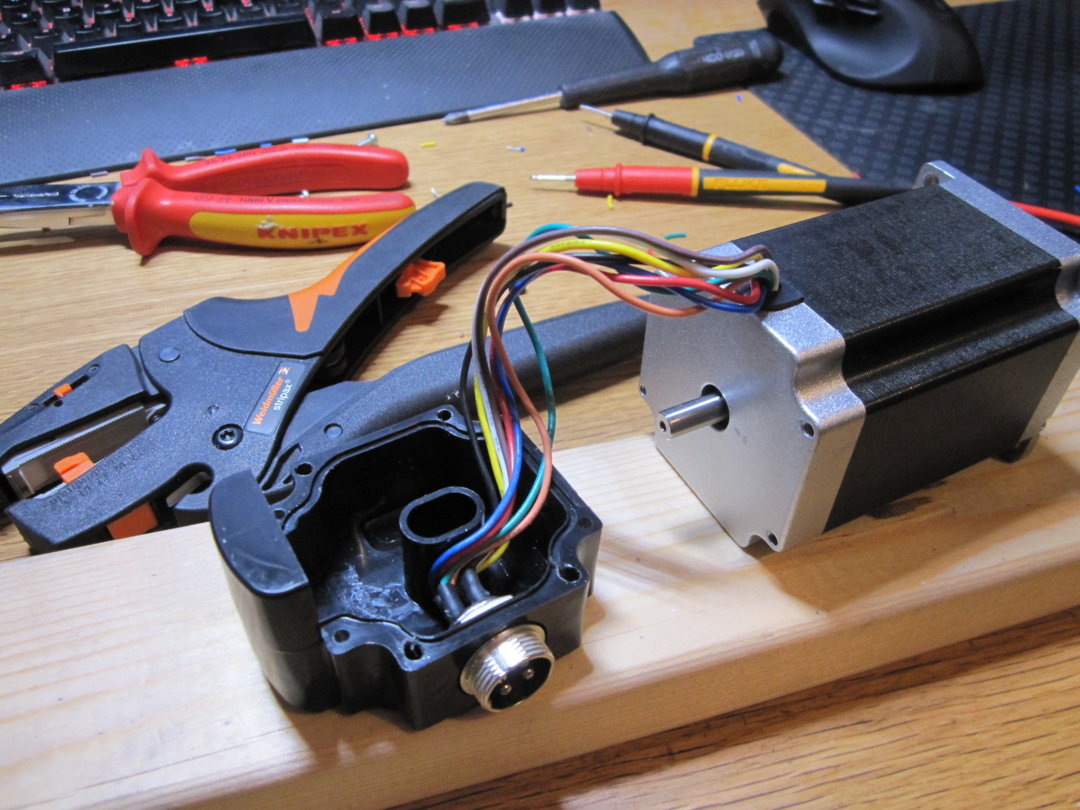
Picked up some 2.2 nm steppers.
Also picked up some rear covers and added "aviation plugs" to them. Definitely like the covers, really makes it look "cleaner" and also protects the rear shaft.
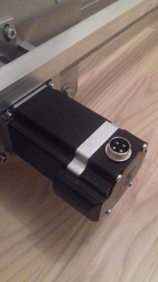
The motors have 8 wires but I just soldered two wires to each plug to run them bipolar parallel. I hope I got that done correctly because I'm not very good with electronics and not very good at soldering, but I think it turned out alright in the end.


I usually prefer screw type connectors but in this case there were no room for those inside the cover as you can see. (Also they are harder to find and much more expensive).
Also decided to use the cheapo mechanical micro switches for now, really should have atleast prepared for them when I build the machine in the first place because I had to take alot of it apart now to get the screws for them in the profile grooves.
Drilled up the holes slightly to accept m4 screws. They are obviously not adjusted correctly or anything at the moment, but atleast they are on there.


With the switches done I put the machine back together again and installed the steppers with the pinions and tried to adjust the racks and that turned out to be difficult.
I got it to where I think it'll work but I'm not too happy with it. It's kinda noisy and seems a little "rough" when moving them by hand. I'm thinking that might be because the pinions are of low quality so I will try to find a set of better ones.


Other then that the next thing to do now is to make a waste board but I can't seem to find any valchromat or even mdf around here that is 12 mm so I'll probably end up using some thicker 19 mm material. It won't look as good as the waste board will then be higher then the corner plats, but oh well...
Also still waiting for the Apex to be released, although that's starting to feel kinda hopeless with zero updates and not even any replies to the forum thread... Still not in a hurry though so we shall see I guess.
2017-11-03
Small update today. Picked up the angle bar (aluminum 20x20 mm) for the cable chain and just finished putting it on.
Went on better then I thought considering it was done with a dull hacksaw, a file and a 18v drill


Rawcnc 1.5 Desktop Edition


This will be the first build I post on here, and also my first cnc router build.
To be honest I don't know how well it fits in here on Openbuilds because it's not my design but a "commercial kit" I guess you would call it and it does not use the Openbuilds v-slot system, but it will use Openbuilds steppers and Apex controller when it's finally released.
I just thought I would share it anyways because I think it's a cool design that I haven't seen posted before.
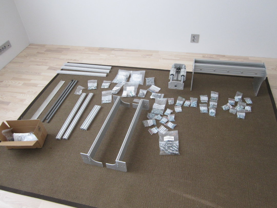
Like I said this is not my design, it's from a Swedish company called Rawcnc, they sell these as prebuilt machines and kits in different sizes and version, or you can buy just the plates.
I bought just the plates that came with a BoM, instructions, drawings etc. They are 280 euros, I find that reasonable considering it's a total of 16 plates and they are made from thick (6 mm and the gantry plates are 8 mm) aluminum.
The goal here is not for this build to be a guide of any kind, I just wanted to share and showcase the machine in the hopes that it could inspire others.
Size
These machines were designed to be rather large I guess and the smallest version that Rawcnc sells are 990x990 mm.
I was originally going to build mine 2000x1300 and house it elsewhere because I live in an apartment, but I changed my mind and decided to make it a desktop machine so I could more easily build and tinker with it at home and then maybe make it full size later when I learned the basics.
The sizes will be:
Y: 650 mm
X: 605 mm
Z: ~125 mm depending on spoil board.
This gives a cutting area of 380 x 380 mm and the footprint of the machine will be wider than the x-axis by the amount of about two stepper motors
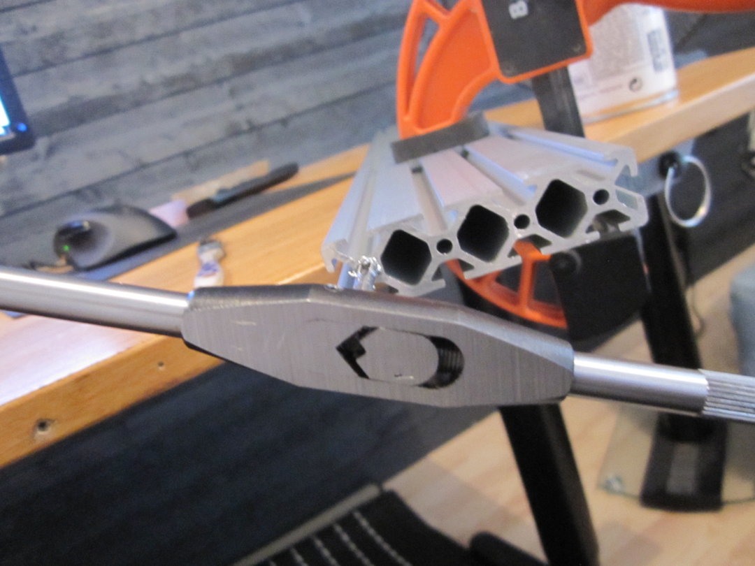
Linear motion
This part is what I think is really cool about this machine!
It uses a type of "shaft clamp" that you press into the grooves of the aluminum profiles and then hardened steel rods go into those clamps for steel u-groove bearings to roll on.
I like this concept more than the v-slot system, it should be more rigid and durable, and if you ever need to replace the rods that'll be easy to do without taking apart the entire machine.
Also there should be little risk of chips and dust interfering with the motion because anything that does land of the small round rods are not likely to stay there

These are just some leftover pieces.
Drive
You can choose to build this with either rack and pinion or a belt drive system, the plates works for both, that's why they look like they do with a number of unused holes.
I chose to use rack and pinion so the machine uses direct drive rack and pinion on the X and Y and lead screw on Z.
I'm not crazy about the direct drive, it's my understanding that you would want some reduction for better resolution so currently in my head that is the biggest concern.
But on the other hand I have seen a lot of pictures and videos (both from the seller and other users) of what these machines are capable of, for example the plates are made by another machine just like this one, I think that's pretty cool and definitely good enough for me, so I still think it'll work out just fine.
Found those videos on youtube, seems good to me!
The build
I had already started building the machine before I started taking pictures and had already done this:

Not a very good picture I know, but trust me, they're square
Yep, that's how I spent that Friday night, Netflix n tapping!
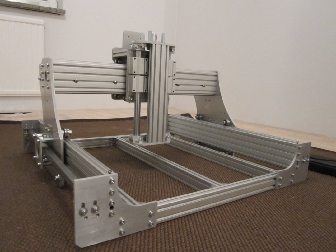
I'm currently doing a complete renovation of my apartment so for now I'll have to do this on the floor in a room that is close to finished.
Frame
The frame is made from 40x20 connected with a bunch of angle brackets and t-nuts. Really not much to it putting it together other than making sure you do it on a flat surface so the profiles lines up nicely.
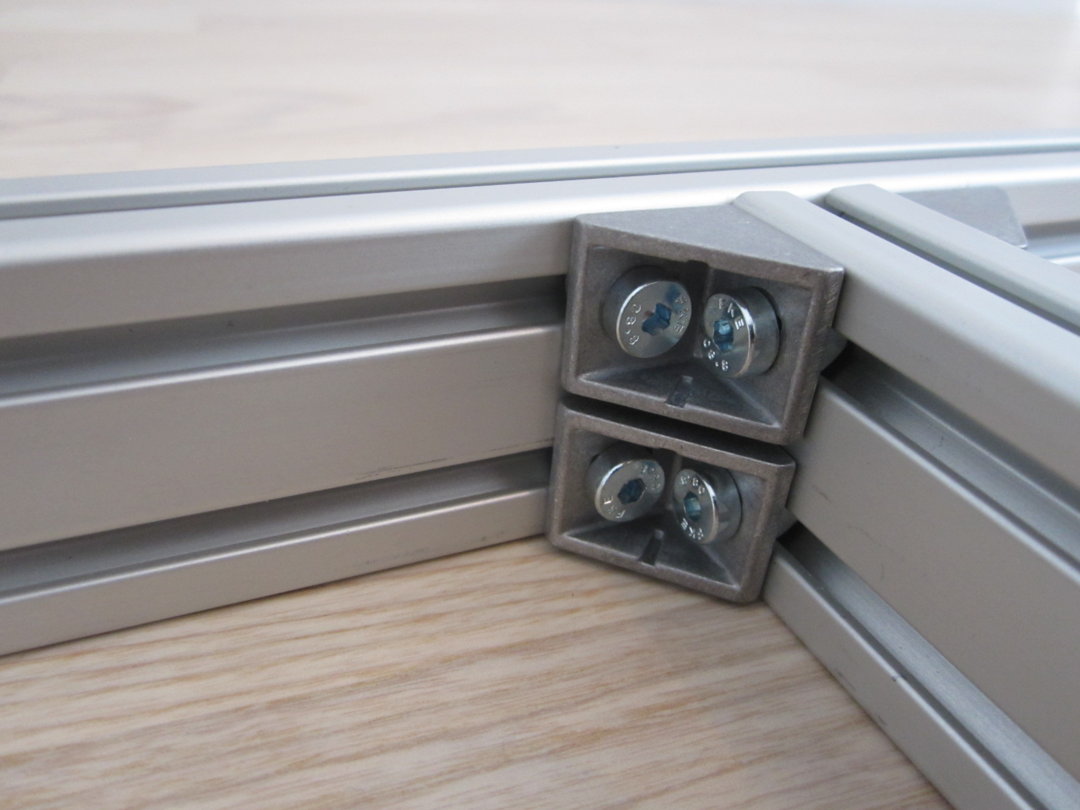
I ended up using these brackets, it's not what's listed in the BoM, these are:


The reason I didn't use those is because I had the wrong type of screw, low head cap screws, as seen to the left. Those do work but just barely and it's very fiddly. What you need instead is button head DIN 7380 from the BoM, works much better.
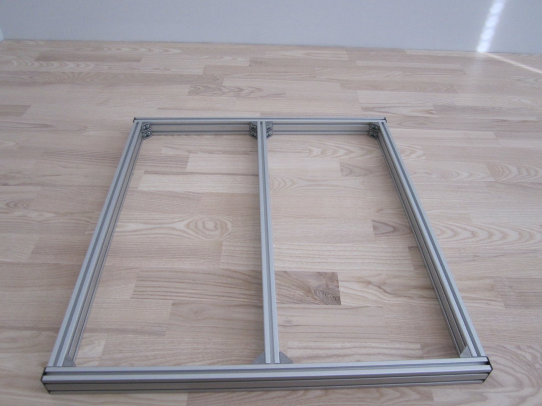
Done and done! (well not really, I screwed up there and the two profiles on the sides needs to be further in because in this picture they are sitting where the y-axis is supposed to be)
Y-axis
The next thing I did was mount the Y-axis (80x20) with the corner plates on the frame.
I like how they attach to the frame with t-nuts, makes it easy to slide to square them.
At first i roughed them in by aligning them with the edges of the front and rear frame profile and then, only having 150 mm calipers, used two pieces of profiles and measured the gap between them and adjusted on both sides until they were parallel. This took quite a bit of time and was probably overkill, I could have just put the gantry on there and adjusted them until they rolled smoothly because there will be limit/calibration switches anyway.

Gantry
The X-axis consists of two 80x20 profiles and a steel tube bolted between them as reinforcement.
I had doubts about that steel tube and didn't think it would be straight enough and looking up tolerances online only confirmed that. It looked like they could basically be dropped from a train and then get run over by a truck and still meet spec...
Anyway I went ahead and ordered some online (gotta love eBay!) because hardware stores around here don't carry them and the closest steel depot is quite far away.
When they arrived I was very pleasantly surprised at how straight they were!
I don't own a real straight edge but I used one of the x-axis 80x20's with the steel rods mounted on them and used that as a straight edge, should be pretty darn straight and there would really not be any point having the reinforcement be straighter then the actual axis of the machine anyway.
Holding those to the tube and a flashlight behind I could see just a tiiiiiiny amount of light in a few spots but I wasn't able to slide my thinnest (.05 mm) feeler gauge in there. Definitely good enough!
The parallelism of the surfaces to be mounted to the profiles I just checked with the jaws of the calipers and it was spot on as well.
The BoM lists a tube with 2 mm wall thickness and to attach it with self-tapping screws.
The tube I bought had a 5 mm wall thickness so I tapped those holes and used pan head m5 screws instead. More work and a drill press would have helped, but it turned out great in the end and this is how the finished result looks like (note that this is the 1300 mm axis I had originally planed to use, I don't have any pictures of the smaller one, but yeah, it's exactly the same except shorter).


Having the tube sit a little bit down like that and not in the middle is necessary because otherwise the screws for it will interfere with the screws on the rear of the front Z-axis plate. It also creates a good surface for a drag chain to be placed on later.
U-groove bearings
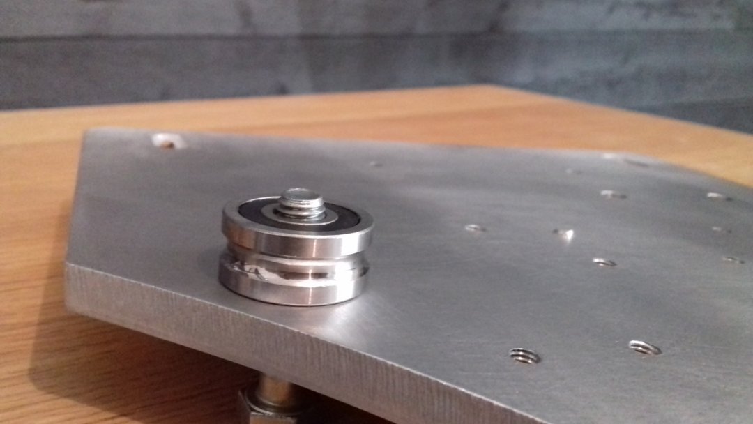
There are 16 of these bearings in total and they attach to the plates using m8 screws with nuts and washers as spacers.
The upper ones on each plate just screws directly into threaded holes and the lower into slots with holes for set screws underneath to tighten them. Works really good, it's easy to snug them up to remove any play.
Putting these on I quickly found the thickness of both standard m8 nuts and washers varies quite a bit.
Therefor I took out the digital calipers and measured every single nut and washer and found combinations of them that added up to the 9.50 mm distance I was looking for and where I couldn't, I added shims to get them as good as possible. After doing this the largest difference between them is now .02 mm.


Not really sure how much difference this made, it was probably overkill again but it feels good knowing they are very well aligned and they do roll really smoothly.
Z-axis
The front and rear plate ride on four u-groove bearings each and are connected with three pieces of 80x20 and there is a 60x20 between the top and bottom plates for the spindle.
The steel shafts are 20 mm and there are two linear bearings for each, slides really nicely, I can't feel any play at all and should be plenty strong.
The lead screw is 10 mm and has a pillow block bearing with setscrews top and bottom and a anti-backlash nut on the plate. Aligning those bearings and through the nut was the only tricky part of the z-axis and it took a little finessing to get it perfect.
To be completely honest I can't wrap my head around why the anti-backlash nut is even required, because it's attached to the plate which doesn't move, but I'm sure I'm missing something...


The BoM calls for pretty much only low head screws. They are certainly not needed everywhere but this location is one of them, it's pretty tight.
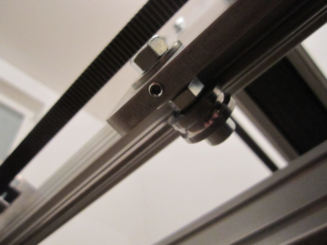
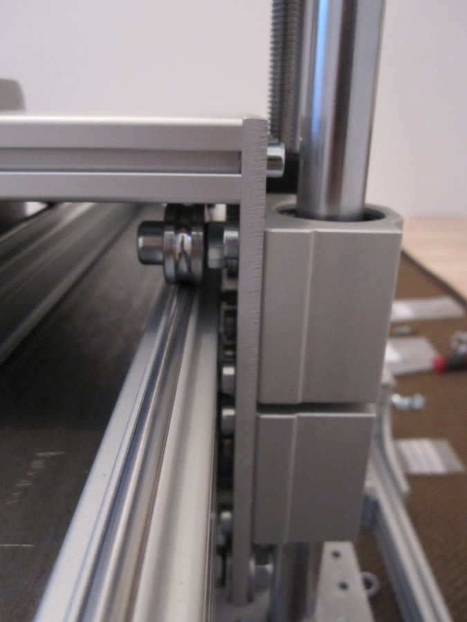
Rack & pinion
This is the way the racks are attached, using brackets fastened to slots in the plates to allow adjustment for different sized racks, pinions and whatnot.


From what I've seen on other machines the steppers are usually attached using some sort of pivoting mechanism with a spring to push the pinion against the rack, but on this machine the steppers are mounted rigidly on motor plates sitting on stand off screws and then there is an adjustable plate with a bearing riding on the rear face of the rack to keep it pushed down against the pinion.


Keep it simple I guess, seems to work well!
To do list
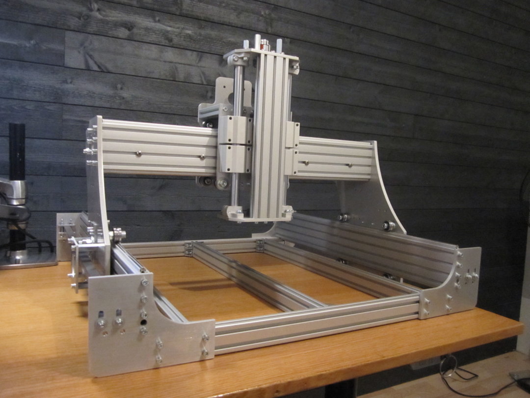
This has been a super fun build and I'm very happy with the results so far, the machine went together nicely and everything slides and rolls silky smooth and it feels plenty rigid.
The only thing left to do "mechanically" now is a spoil board and an angle bar between front and rear corner plate on one side to put a drag chain on, like in this pic:
I still need to do all the electronics including motors, wiring, drag chains, limit switches and a spindle.
The switches should have been installed already at this point, but I'm considering using proximity switches instead of mechanical micro switches which is why I havn't.
For the spindle I'll probably start out using a Dewalt palm router that I already have.
As far as a controller goes I was planing to wait for the Apex to be released, but now that I've gotten this far I'm getting really excited to bring this beast to life so it's kinda tempting to go with something else, maybe just arduino for now
Really though, I'm not in a hurry, lots left to do with the apartment anyways to keep me occupied so I'll probably end up waiting a bit longer for the Apex.
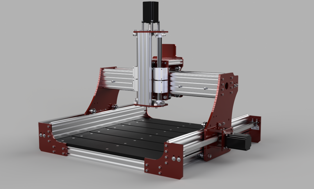
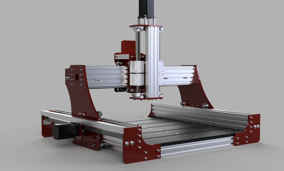
Here are just a bunch of random pictures. The renders won't be spot on, those are from a Fusion 360 model I made just to start learning that software and I don't have dxf-files for the plates so I just kinda modeled those by eye and got lazy and didn't include all the belt drive features.


Had to see if it would fit on a desk!


Close-up of those beautiful shafts!


More to come!
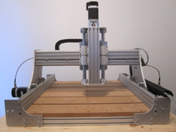
Rawcnc 1.5 Desktop Edition
Build in 'Cartesian Style CNC' published by roadss, Jul 11, 2018.
This will showcase the build of my Rawcnc 1.5. A rigid cnc router from the Swedish company Rawcnc, featuring a rather cool linear motion system, rack & pinion and steel reinforced X-axis capable of milling aluminum.
-
-
Build Author roadss, Find all builds by roadss
-
- Loading...
-
Build Details
- Build License:
-
- CC - Attribution NonCommercial - CC BY NC
