
Why "The Ronin OX"?
I started this CNC project because quite simply, there is no reasonably priced commercial CNC machine on the market that can be easily adapted to mill carbon fiber and G10 safely and efficiently.
8 months in the making, the "Ronin" OX CNC build was ultimately a test to find an answer to a question....Can Openbuilds machines compete in a real fiber composite production environment with other commercial routing machines using purely open source hardware and software at a fraction of the cost?
The answer is yes, absolutely.
After months of research, in my assessment, the OpenBuilds design platform is FAR superior and cheaper than the Shapeoko 2, Shapeoko 3 and X-Carve, and far more adaptable.
Without getting into too much text-heavy description, here is footage of the Ronin OX in action doing some of job shop runs at Ronin Energetics. (*insert shameless plug) Our shop is now producing our first fiber composite products, all thanks to the awesome OpenBuilds community where so much open information was posted it was possible to learn, build and adapt the OX to make this possible! Check out some other videos on our YouTube channel for more machining and laser action! Enjoy!
Check out more carbon fiber machining videos and pictures on our instagram and facebook! If you like these types of videos please like and follow us, a lot more to come!
@roninenergetics
Ronin Energetics Facebook
The Ronin OX is almost a totally stock OX reference design with only a few inexpensive but absolutely crucial modifications needed to turn this thing into an absolute carbon fiber shredder. I've summarized the main take-a-ways from this post here at the top and will elaborate on each in the body of the article. If these are adhered to, anyone can turn a plain reference OX build into a work of art that can quickly and safely mill fiber composites.
The Build
- Belt Tension. Belt Tension. Belt Tension. (also belt tension)
- ABS Water table with elevated fixtures.
- Simple X & Y gantry reinforcement.
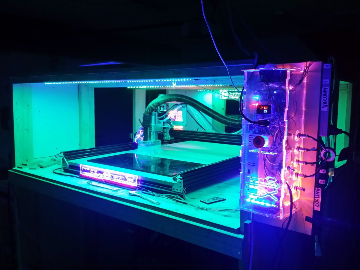
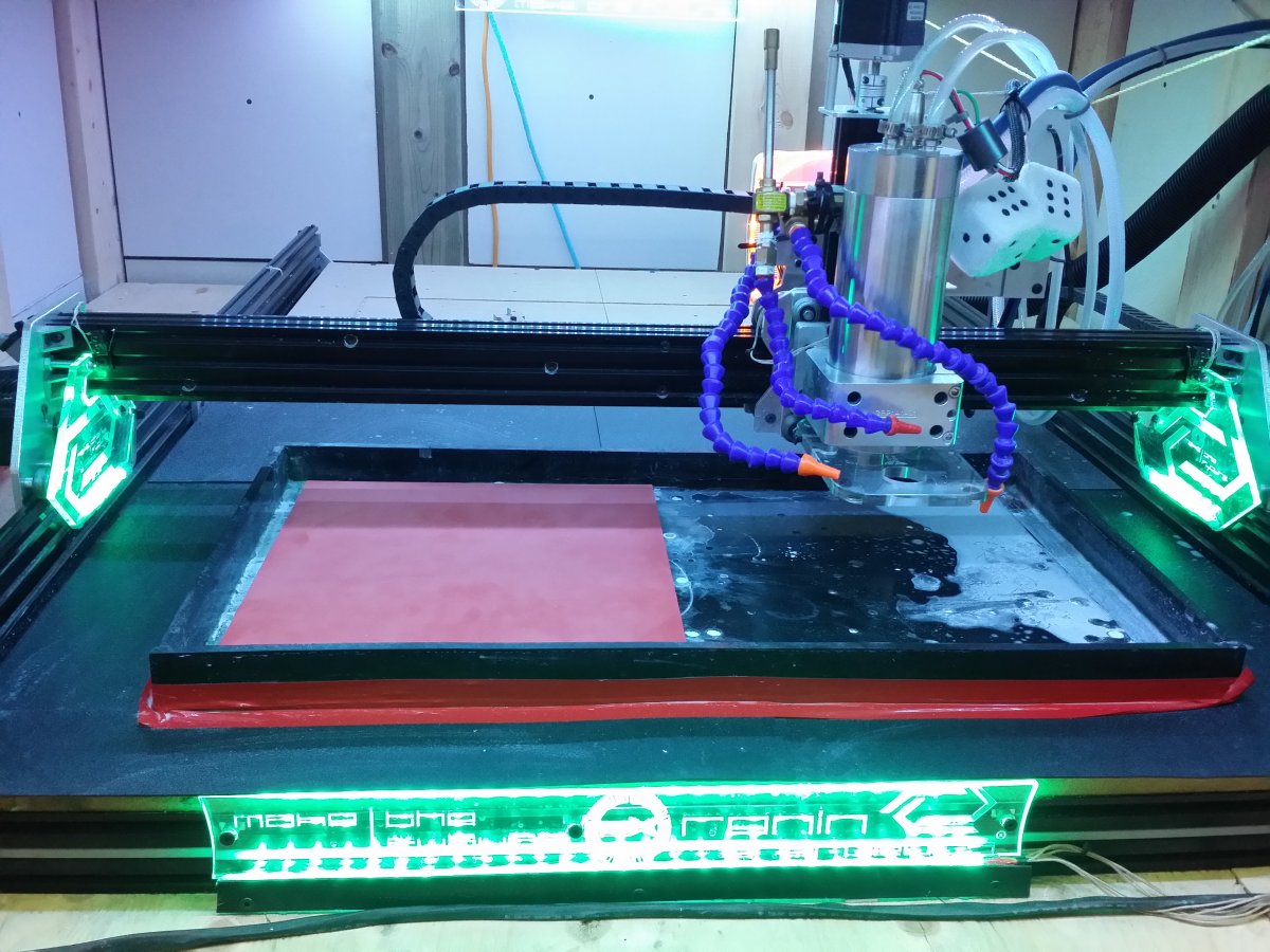
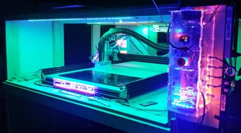
Pictures say 1000 words so here ya go! The Ronin OX is 1500mm x 1000mm with 262oz-in Nema 23 motors controlled by a TinyG motion system, and CAM'd with Fusion 360. If you really like this build please remember to rate it 5 stars, our next custom build will be based around the awesome C-Beam! Thanks!


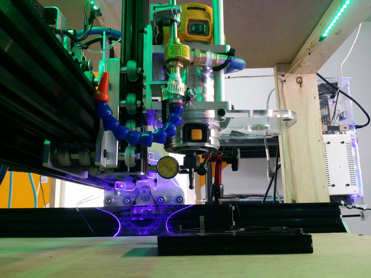
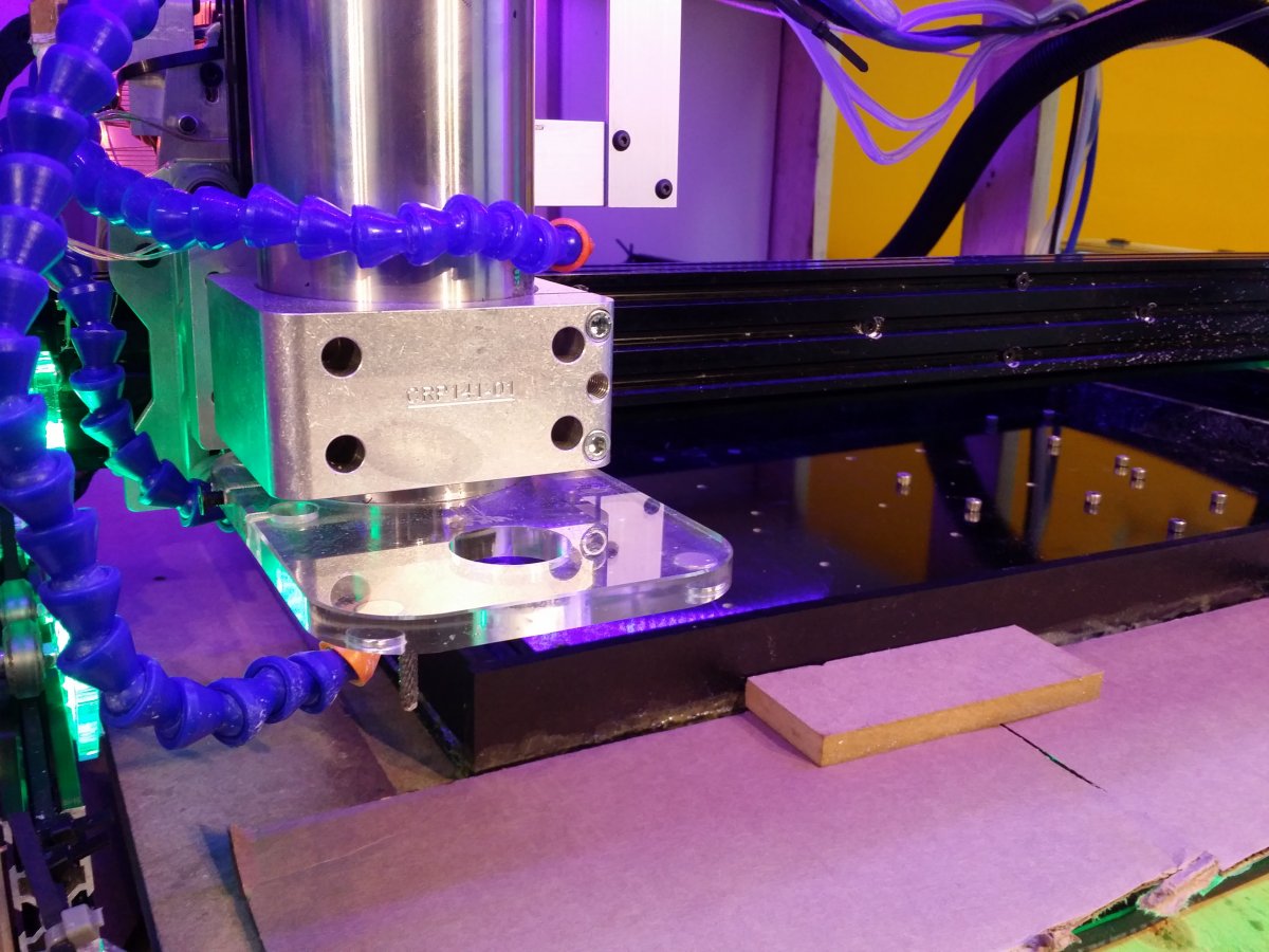
The Ronin OX has long since had the DeWalt router removed due to a massive 0.3mm bore runout which led to repeated breaking of bits. Also in view is a vortex tube (Vortec brand) sourced from Pelmar Engineering in Canada. Attached to a 4CFM @ 90psi air compressor. A vortex tube gets extremely hot at the top and extremely cold at the bottom air blast. Great for milling Al dry. And by cold, the air blast really gets cold. Also in view is the positively magnificent magnetic dust shoe attachment by Chris Laidlaw. (who also did a fantastic job milling our gantry plates)


The 2.2kW Spindle + VFD Upgrade
Simply put, this chinese spindle works flawlessly. ER20 nuts are a joy to work with doing tool changes compared to the DeWalt. This one required a 220V connection which hooked up nicely to a standard 50A welding plug. (did not come with any wiring) The manual, believe it or not, is actually easy to understand and has some fairly useful features such as tweaking the Voltage/Frequency curves to provide more low end or top end power. Since it is water cooled, it can run as low as 8000 RPM and can probably be pushed to 6000 RPM if the torque curve is pushed all the way to the low end. In the event that these spindles stall out, the over-current detection works quite well and the inverter shuts everything down safely. You can also see in the picture that Chris Laidlaw's dust show actually fits perfectly with the bottom lip of the spindle. I drilled extra holes through the side of the plate and used 5mm screws to hold it firmly in place.
The primary reason to go with this spindle is the high top-end torque it provides which is needed when milling fiber composites. Milling/routing composites is an abrasive/shearing process and chips are not created, only dust. The best results are obtained (in my experience) when you use high rpm (24k) and very high heat dissipation (flood coolant). Wiring is quite straightforward, check out the site below as a resource on this spindle, its one of best I've found online so far. I also earth ground the spindle casing itself as a safety precaution.
2.2 kW (kilowatt) Water Cooled Spindle
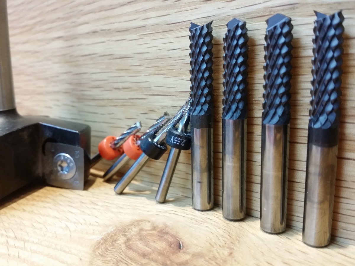
I also consider CVD Diamond Burr tooling a necessity now doing production after destroying standard carbide endmills in around 250 linear in. each. Milling fiber composites with standard carbide fluted endmills is the equivalent of rubbing the edges with sandpaper at 20,000 rpm...However you can get away with carbide burrs which will start getting dull around 3000 linear in. of cutting.

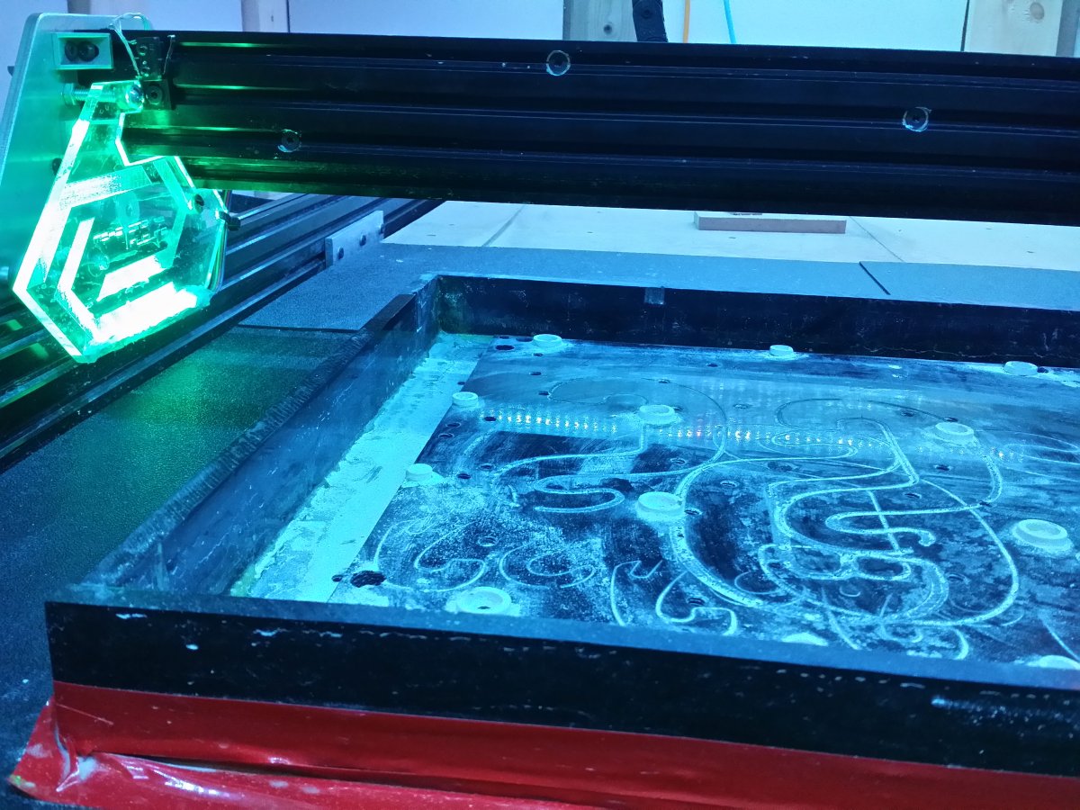
The ABS Water Table
The water table itself is integrated with an aluminum fixture which was faced to keep the Z-axis zeroed. The very bottom layer is a 30" x 15" 3/8" thick ABS plate. On top is a 12" x 24" aluminum plate and screwed on top of that is another 12" x 24" 3/8" thick ABS plate on which 1/8" ABS standoff spacers are cemented. The ABS washers/spacers were cut on our laser out of scrap abs sheet. The reason for the spacers is to prevent delamination with is the death knell of milling fiber composites. By plunging past the bottom of the stock by a considerable distance, around 2mm or so, the edge finish of the G10/Carbon fiber comes out nearly perfectly with the edges completely intact. if the stock is flat on the bed, the sludgy swarf starts packing into the trench and can break bits. By elevating your fixture, your "chip" evacuation is very solid. (Also note where I've drilled, tapped and bolted the X beams together. This has helped X-Y ridigity a lot. The water pumps themselves are $10 specials from Princess Auto(Harbor Freight for Canucks), simple 12V bilge pumps tied directly into an ebay buck converter connected to the TinyG 28V power supply. The flex hoses can also be found in cheap packs of 8-12 off of ebay for quite cheap. The water drains from the bottom and is repumped back onto the table. The G10/carbon fiber dust is actually quite heavy and sinks to the bottom of your water container. By making sure the drain hose goes right to the bottom of your water tub and by keeping the pump near the surface, you can use the water quite efficiently without needing a change. When that time comes it is easy to dump out the water and bag up the silica/carbon sludge and dispose of.


A Note About Machine Rigidity
This is by far the biggest problem with large aluminum extrusions, they are nice and light and don't rust, so awesome for flood coolant systems. However, the spindle on this machine is 11 lbs alone, plus it has the entire weight of the x gantry being hauled around. This deflection can be thought of by grabbing the Z motor and pushing it forward an back and looking at what happens to the angle of the endmill. Also note in the above picture the Aluminum plate attached to the inside to the Y- beam. This is nothing more than a metal plate with a triple L-bracket from the openbuilds store bolted to the table. So is it possible to overcome most rigidity issues when machining fiber composites purely with CAM techniques? Absolutely. Main points summarized below:
- Elevate your fixture, and cut the composite in a single pass with a DOC(depth of cut) of 1 x Dia. of tool. Don't take shallow passes, even if this means going at a slower feedrate. This seems counter-intuitive because most cnc'ers are used to cutting metal such as aluminum which has entirely different rules and the only way to avoid bad deflection is to take fast, light, shallow passes. For milling composites with a machine of questionable rigidity, the opposite needs to happen. This technique should only be attempted with flood coolant and burr tooling. This also prevent the huge amount of sludge/swarf from packing under your endmill because you are utilizing the full side edge of the tool to cut.
- When drilling holes, use "Bore". Do not just plunge. In Fusion 360, I typically drill holes with a tool at least 50-75% smaller diameter than the hole I want to drill. Then I use 0.2mm pitch at around 600mm/min feedrate. This technique makes nearly perfectly drilled holes with zero delamination. As always, elevating the fixture is a must and I always bore past the stock bottom by at least 1-2mm.
- The Lead-In. How do you plunge into the material properly when you aren't supposed to directly plunge? The answer is to predetermine your lead-in entry positions in the CAM either by pre-drilling lead-in holes, or to use a shortcut and lead-in directly on top of one of your tabs no faster than 75-100mm/min. Most tab heights in G10/CF only need to be around 50% of the thickness of the stock. By slowly plunging directly over a tab, what the machine ends up doing is to make a small trench as it follows the 2D Contour to the end of the tab, then it slowly plunges the rest of the way. This technique avoids deflection in the Z-axis doing the plunge to the final depth before continuing with the 2D Contour toolpath at 1 x Dia. DOC. Ramping at around 5° is another technique that is acceptable but I find it is inefficient and doesn't give the best edge finish.
- If milling 1/4" plate with 1/4" tools, use conventional cutting. Do not use climb. Due to the lack of any "chip", the advantages from climb milling in edge finish are not terribly apparent. I've broken a number of tools trying to climb mill 1/4" G10 plate. Burr tooling is inherently more brittle than standard endmills due to their very large amount of teeth per unit area. Any Z deflection in your gantry makes the using climb milling on thick G10 plate a non-starter. With the Ronin OX, the rigidity is sufficient to mill 1/8" thick G10 with 1/8" dia. burr tools using climb with no issues.
- A note about tools. Drill point plunges easiest, Fish-tail gives your the nicest edge finish. Depends on what you are going for. I don't recommend flat burr endmills. Disadvantage of both and advantages of neither. Here is a great site on composite machining. Why Chipbreaker and Diamond-cut Routers are Better for Machining Fiberglass and Carbon-fiber Composites
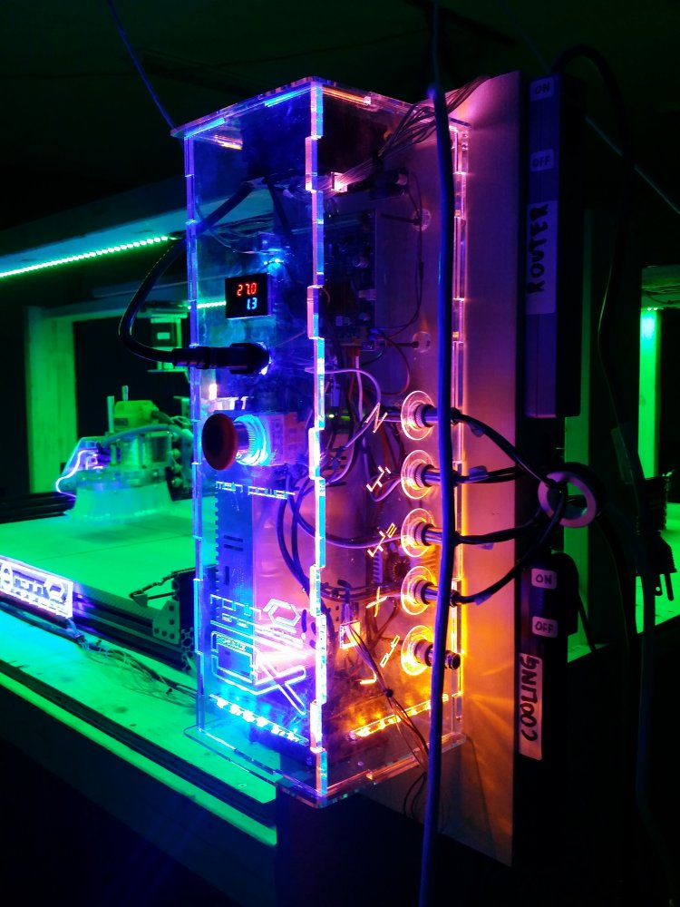
The Electronics
At the heart of the electronics is the TinyG v8 motion controller and Chillipeppr software. Heatsinks were added on all the motor drivers as I run the current pots totally maxed out at 2.8A or so on the 262 oz-in NEMA 23's on all 4 axes. I run at 1/8 microsteps on XY and 1/2 microsteps on Z. XY Jerk accel. is 5000, and travel rate is from 1000-3000 mm/min. It can be pushed faster but when only milling fiber around 20-40 IPM, there really isn't much point to push it. Some points to mention about the TinyG and electronics:
- Motion planning and jerk/acceleration customization is a breeze though Chillipeppr and once tweaked, that thing can really move those motors around. Spend the time to tweak it right for the rigidity of your build.
- Use the shortest possible USB cable you can find. Any cable over a couple feet can make the serial comms really twitchy.
- Use shielded wire on all homing/limit switches, or at the very least run the homing wires far away from your stepper motor wires. The potential for twitchiness in the homing/limit wires on the TinyG is its biggest drawback. Getting the homing jerk accelerations tweaked properly in Chillipeppr can also be a real pain so MINIMIZE EMI wherever you can. It will save you hours in the future....Also put ferrite toroids on all the stepper and spindle motor wires and remember to earth ground your V-slots. This actually makes a difference in preventing noise in the homing lines I've found.
- In Chillipeppr, if your machine ever gets a jitter, stutter or stall when running gcode, turn off the realtime 3D viewer first. There are a multitude of gcode sending tweaks in Chilipeppr but in my experience, the 3D viewer can put a huge strain on the browser and can directly cause interruptions in the gcode, even on relatively new computers.
- When you login to Chillipeppr, it always saves the previous job. This seems minor but is actually quite handy when doing production while juggling multiple revisions of revisions of gcode files.
- Once you understand the settings and what they do in Chilipeppr, the easiest and fastest way to modify the TinyG is to just use a text file. Super simple to set different layers, ie) G54, G55, etc. I'll elaborate on this in a future update along with the gcode sending settings that work best for me.
- Put heatsinks on your motors, and a fan blowing across the TinyG. They all get very hot after an hour of running a job. Especially the Z-motor. I've cannibalized all the heatsink-fans for the Ronin OX from old computer power supplies and electronics garbage in general.


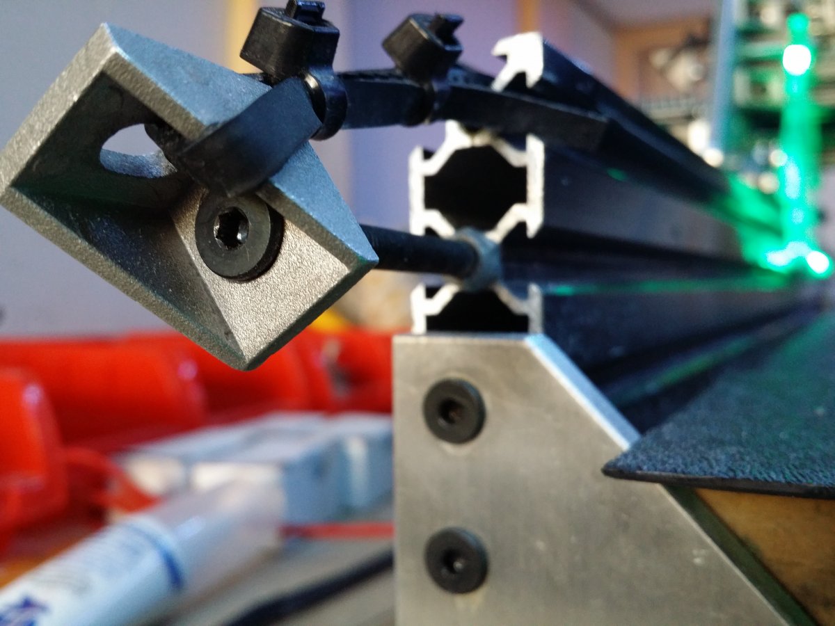
A Super Simple Ox Belt Tension System
I can't stress how important it is to preload the OX belts with considerable tension on both ends of the belt. Without needing any special or complex highly machined parts and a few bucks from the OpenBuilds partstore. Basically a long screw, 3 lock nuts, and a corner/L-bracket per belt tensioner. 4 on the y-beams and 2 on the x-beam. Pictures below say it all. Best way to go about it it is to loosen all the lock nuts slightly after the assembly is in place, loop the belt through and zip tie as tight as you can go, then start unscrewing the long screw the preload the belts. Stop tightening when you think the belt will actually snap. It is now sufficiently tight. Then tighten up all the locknuts on the belt tensioner assembly.
Yes your belts will stretch and yes I now consider belts a disposable, but you can get easily 6 months of hard machining out of them before needing a replacement belt, probably longer. Its worth it to really rigidify the machine.


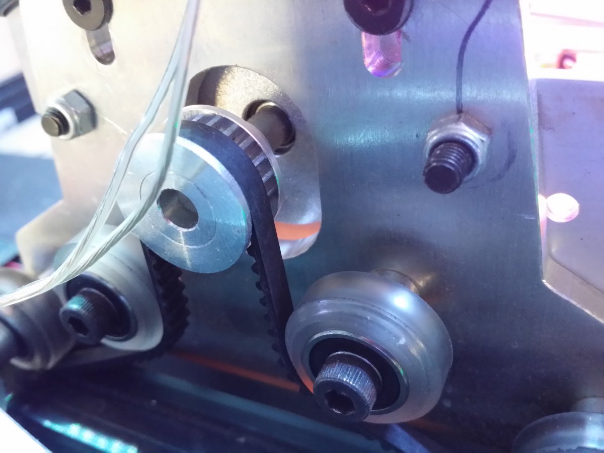
Bonus Mod: Add Idler wheels to the X Gantry
This mod was done to increase the tooth engagement in the X-axis because that single motor is hauling a lot of weight with that 2.2kW spindle, plus the entire Z-motor and assembly. No extra holes need to be drilled, Chris Laidlaw's OX plates can be adapted in place, just add 2 extra solid wheels as seen below and that's it!

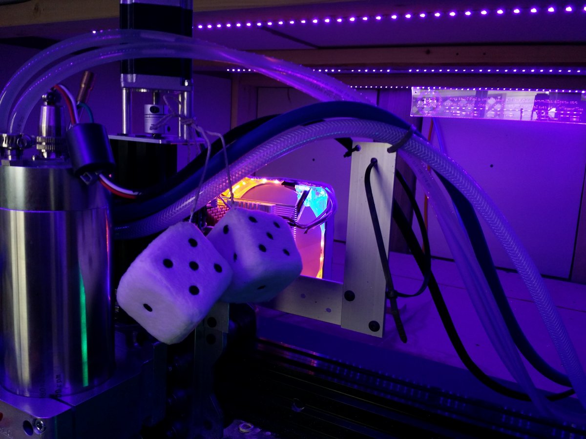
Bonus Mod: Add Aluminum Cable/Hose Keeper
With 2 coolant lines going to the spindle, an air compressor hose, and a flood coolant hose, plus sometimes a shopvac hose, a strong assembly was needed to keep it all out of the way of the cutter. A hole or two was drilled and tapped in the x gantry plates and 2 cheap pieces of Aluminum plate were screwed together to make a very nice and effective cable keeper. A line of twine was run from front to back and tension adjusted to keep the cables taut enough to hold in place but loose enough to not move gantry around accidentally. (Also the dice are a crucial addition. Everyone knows CNC's run on sweg)

So can this thing actually make stuff?
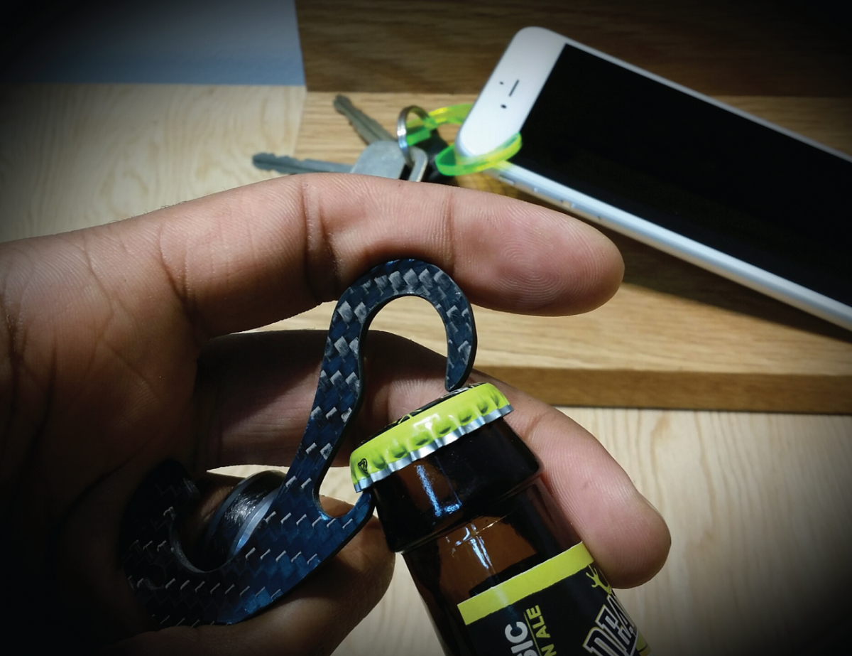
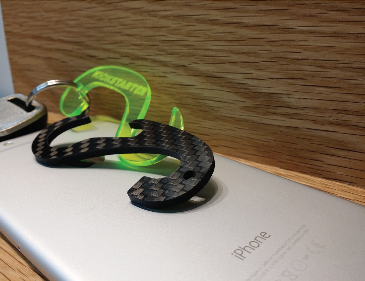
Thanks for reading this far! I have tried to disclose most everything I know about how to mill fiber composites using only a few straightforward mods to the reference OX design. I believe carbon fiber machining has the potential to become as accessible to makers in the near future as aluminum already is today, if it's machining can be demystified. Because silica and carbon dust is a huge respiratory hazard, I must advise that it should always be cut using either flood coolant or with wearing a sub-micron respirator and a solid vacuum system.
All the items shown below were machined on the Ronin OX with a minimum of post cut finishing. One is a fiber composite EDC multitool/smartphone/tablet stand/bottleopener (TheMiK) and the other is a pre-production prototype of a fiber composite tactical utility hook (TheMARK). All 100% machined with OpenBuilds hardware and open-source software. I unfortunately don't have hard numbers on the cost of this build due to all the random mods, but including the compressor, vortex tube, DC spindle+VFD, power electronics and other accessories, the grand total is less than $3k CAD, which is less than what you'd pay for a simple spindle upgrade on most commercially-sold table routers...Thanks again for reading this far and ask me any questions in the discussion! Happy building!


RONIN OX | The G10/Carbon Fiber Hogger
Build in 'Cartesian Style CNC' published by alex_b, Nov 19, 2015.
The Ronin OX is a dedicated fiber composite milling machine. I give a complete in-depth article on how to take a nearly stock OX build and easily turn it into something that can mill carbon fiber and G10 plate effectively and quickly.
-
-
Build Author alex_b, Find all builds by alex_b
-
- Loading...
-
Build Details
- Build License:
-
- CC - Attribution Share Alike - CC BY SA
Reason for this Build
A dedicated fiber composite production machine for our machine shop.Inspired by
The original OX reference build and the whole OpenBuilds team as well as Chris Laidlaw for his great supply of gantry plates. Thank you all! -
Parts list
Qty Part Name Part Link Comments 0 Link

