
02-10-2014
Why call it a Buffalo?
Well, here in Thailand one doesn't see many Oxen but Buffalos plenty. The buffalo is a true workhorse and used for all kinds of jobs.
My intention is to use this machine not only as a CNC router but also as a CNC plasma cutter, laser cutter, 3D printer, plotter and drag knife. For that I have to come up with a handy multi function Z axis that takes all kind of attachments for the various tools. At the moment I have not yet worked out exactly how that is going to look like, but in the back of my head slowly but surely the plan is coming together.
For now I have nearly finished the mechanical part of the build and am busy with some final little tweaks to get it as good as I can get it.
I thought it would be a good idea to try the use of a kind of servo belt for the X and Y axis, which hopefully improves the accuracy of the machine. I designed a "servo belt clip" for the Y axis, of which a .stl file can be found under the files tab. Also I designed a gantry plate cable clip/cover that snugly fits into the hole where the cables of the Y axis stepper motors go into the gantry V-slot (hope that makes any sense), that .stl file is also available under the files tab.
For more info on the Servo Belt look here:
03-10-2014 Update
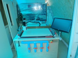
The Buffalo has come to live! Installed this afternoon the electronics and tied it all together. Plugged the USB cable into my Macbook with Parallels Desktop and windows XP on it, installed the CNC USB Controller software of Planet CNC, power supply on and all lights went on. Did the basic settings to test the steppers and movement and jogged happily around the board.
Hopefully I manage tomorrow to tidy up all cabling and get the electronics worked away in some kind of box under the table so I can start doing some initial test cuttings. Like Hola!
Many thanks again to everybody that shared information here and special thanks to Mark and crew for all the good work they've done to make this possible.
Of course I will share as much as I can here to help others out for their builds. A bit of patience though, pictures and other information are on the way but need some organization to make sense.
08-10-2014 Update
The experiment with the so called servo belt worked out very good. Today, however, I experienced strange sounds while cutting a board and clearly one side was out of whack. Checking the sound I got the impression that the servo belt was out of line and the teeth of the belts were grinding onto each other. Took them out, just to find out that actually the slave stepper was not working due to the motor driver that somehow blew up (stopped working, did no more, passed over to the other side etc.). So off to get a couple of them (spare parts never hurt).
Sine I cannot mill anything because of this, I decided to get my X axis perfectly square (it was not bad before, just 1.5mm difference) and had to add a ultra thin V-slot cut off to the 20x40 on the gantry as to get it perfectly square. I now have only 0.35mm difference between the two sides of the Y axis (measured from front and back). Hope that will do for optimal cuts and that it will stay that way.
I also designed a two part clipping system for the timing belts on the Y axis. The STL files will be under files above. It works as follows;
1.
Put the belt in the V-slot profile on either end and fold the end double so you will have a kind of loop on the end, length of the loop should be around 40-50mm.
2.
Stick about 20mm of the loop in the hole below the top groove in the V-slot profile and slide part B into that same hole. This way you will lock that loop into that hole.
3.
Now, lead the belt into the upper V-slot groove, go under the wheels of the gantry side plate, over the pulley and again under the wheels to reach the other end of the X axis V-slot. Again make a loop of around 40-50mm (measure to be sure!) and cut of excess belt. Fold the loop around the front side of the profile while keeping as tight as possible. Work the loop into the hole on the front, slide part B into the hole to lock the loop in there.
4. When the belt is nice and tight take part A and slide that into the top part of V-slot (it might need a bit of hammering in, since it is very tight designed to stay in!).
Voila! The belts are mounted and tight without using a screw having at the same time a nice end cap on your V-slot profiles.
10-10-2014 Update
Today, after some more tweaking and jury rigging of the motor drivers, managed to make The Buffalo move in an orderly manner. See video her under:
Also designed a support for the 45mm wide drag chain on the X axis. Simply push in v-slot and twist 90 degrees to fasten. Contains a hole for a tie rip to secure the drag chain. STL is in the files list.
-
-
Build Author Paruk, Find all builds by Paruk
-
- Loading...
-
Build Details
- Build License:
-
- CC - Attribution - CC BY
Reason for this Build
I want it!Inspired by
Dunno! -
Parts list
Qty Part Name Part Link Comments 2 Black V-slot 20x80 -- 1500mm http://openbuildspartstore.com/black-v-slot-20-x-80mm/ Link For the Y axis 3 Black V-slot 20x60 -- 1000mm http://openbuildspartstore.com/black-v-slot-20-x-60mm/ Link 2 for the gantry ( X axis) and 1 for the Z axis 3 Black V-slot 20x40 -- 1000mm http://openbuildspartstore.com/black-v-slot-20-x-40mm/ Link 2 for the back and front support of the Y axis and 1 for the gantry strengthening (X) 2 Black V-slot 20x40 -- 1500mm http://openbuildspartstore.com/black-v-slot-20-x-40mm/ Link For the spoiler board support 4 Side plates for the gantry, plates for Z axis http://www.ebay.com/itm/Openbuilds-OX-CNC-Gantry-Plates-U... Link Good quality 1/4" aluminum plates, well finished 1 Nema 23 threaded rod plates for Z axis http://www.ebay.com/itm/Openbuilds-OX-CNC-Universal-Z-Axi... Link Good quality 1/4" aluminum plates, well finished 28 Solid V wheel kit http://openbuildspartstore.com/openbuilds-solid-v-wheel-kit/ Link 2 x 7 for the gantry side plates (Y axis), 8 for the X axis plates, 6 for the Z axis. 4 Nema 23 stepper motor http://openbuildspartstore.com/nema-23-stepper-motor/ Link 2 for Y axis, 1 for X axis, 1 for Z axis 4 Stepper motor driver TB6600 4.5A http://www.ebay.com/itm/TB6600-4-5A-CNC-Engraving-Machine... Link Count on 30-35 days delivery from China. 1 CNC USB controller including software http://openbuildspartstore.com/cnc-usb-controller-mk2-4/ Link Very nice kit 6 Micro limit switch kit http://openbuildspartstore.com/micro-limit-switch-kit-wit... Link 2 for each axis 30 GT3 timing belt http://openbuildspartstore.com/gt3-timing-belt-by-the-foot/ Link used for the "servo belt" type timing on Y and X axis 0 Link -


