
Updated 9-4-17
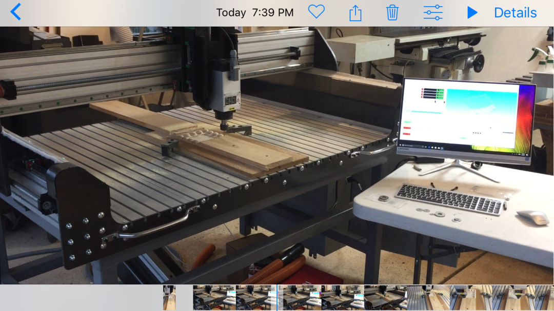
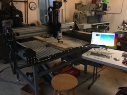
This build is for all intents and purposes complete (I suppose it is ok to change status at this point - as we did a test run on it today). Only a few details remain to be sorted out.
All in all I'm really happy with the results. There were some concerns I had about making a machine with an 8" z travel and a 4' gantry width, but so far it is working out well.
I had reasons for designing the router this way, though I've not talked much about these, except to say that I have two more phases in this build which required I design a taller gantry.
At day's end I want a machine that will work very well for unique relief carving projects. In the end I hope I achieve what I'm aiming at. For the time I'm encouraged to see that this is carving at near full extension down, at center of gantry without any chatter/vibration.
The piece below is nothing impressive (just a leftover piece of pine I had carved with an ornamental piece I downloaded and patterned from grabcad). The detailed areas are fuzzy when viewed up close (as it is pine), but the center is very smooth (and that's where I would've expected any vibration to be noticeable if it were an issue).
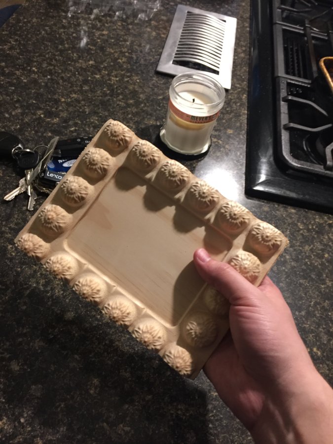
This test relief is about 5/8" deep by 6" by 8". I ran the spindle full speed (18000rpm) with a feed rate of about 150 ipm using an 1/8" ball nose endmill taking .01" passes across x. This took around 55min total. The Z motor was working like crazy on this and it was hot to touch toward the end, but you could still hold your hand on it without burning (I'm told that is not an issue at all; that these steppers can heat up to close to 100deg C before exceeding their limit).
I'll need to read up and experiment with feeds/speeds/materials/surface treatements/materials/etc. that's going to be another arena of learning for me (as I come from a machinist/machine designer background - not a wood worker background), but I'm excited to continue learning.
I am also wondering if there isn't a way to get some more speed out of the steppers? Right now these top out around 225 ipm. Im limiting them at 200 actually. There are issues when we try to run them any faster (they fault). Any recommendations on ways to overcome that are very welcome.
Thanks all for the help along the way!
-JP
Updated 5-7-17
It has been a crazy past two months for me: I crashed my car, moved; helped my parents move and got a new job. Needless to say - with all that and 2 kids (plus doing major OT at work) it has been hard to get much done these past two months. Here are where things stand at present though.
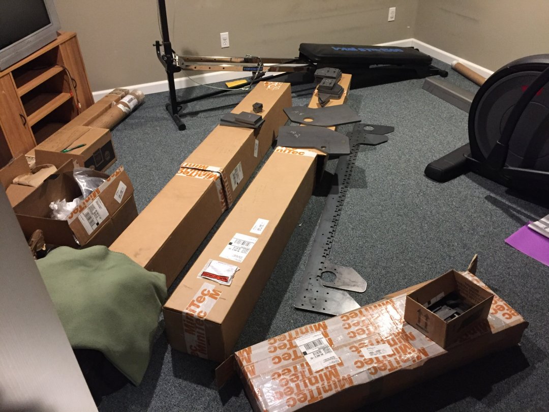
We decided to standard machine gray on the base with black and red hammer paint for the table items. Final colors will look something like this:
The pics below shows most of the painted components (base, guards and front/rear plates against the wall) and everything else waiting patiently in its respective box to be assembled:
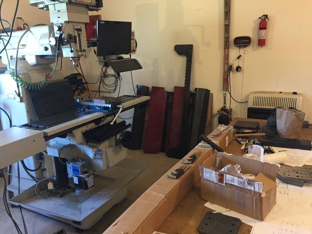
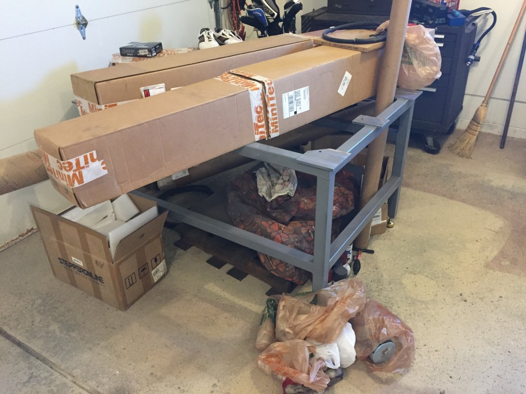
Machining all the machined items really won't be too bad. My dad will tackle the bulk of the machine work bit by bit throughout the next few weeks. We will be held back on the spindle plates for a month or two I suspect, but we will get there.
The biggest problems we face right now are getting our motors to work properly with Mach3. I posted some questions related to a problem we were seeing with these in the forums; but I'll repost the issue here in case someone comes across this first.
First - here is the general setup we will have for our motors (I only have 2 out presently; we were running these as dual x-axis motors; with one on a slave axis):
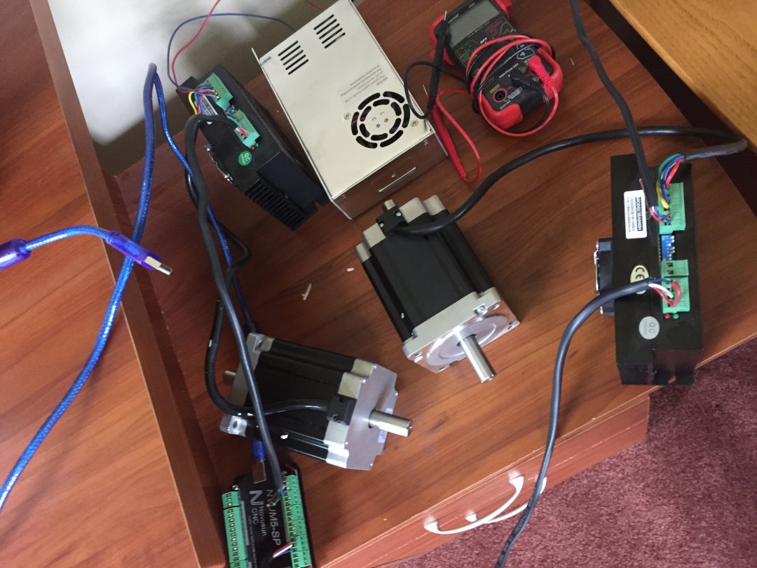
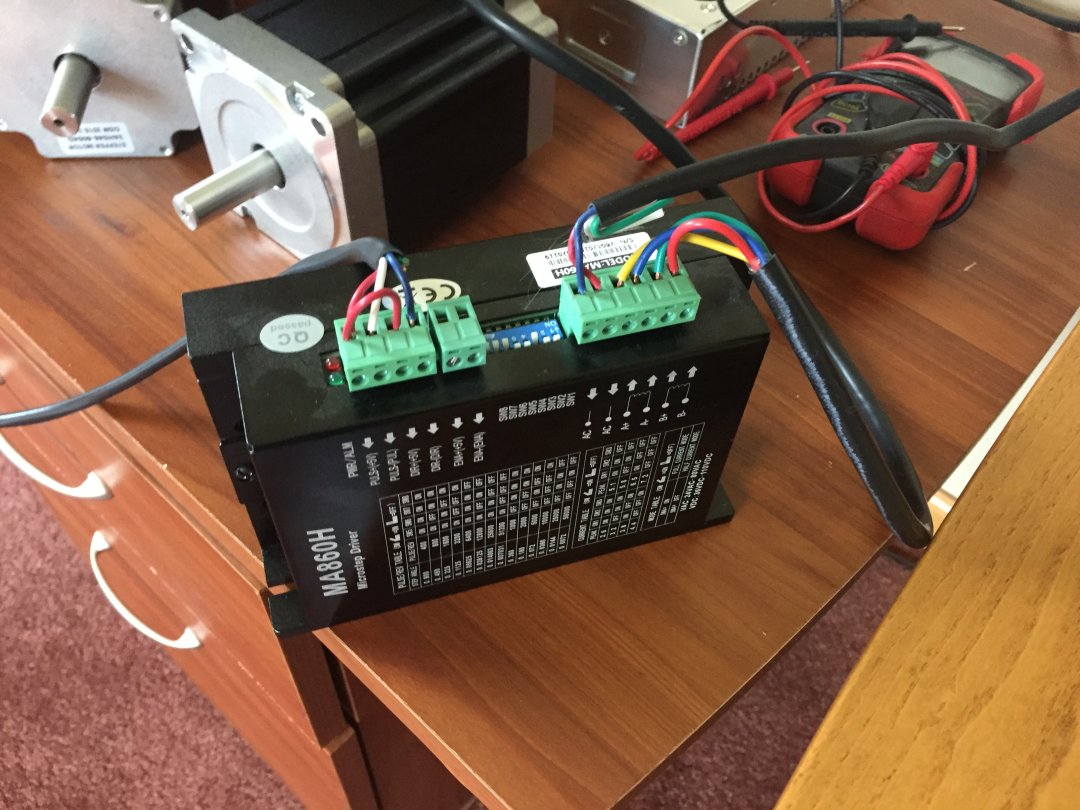
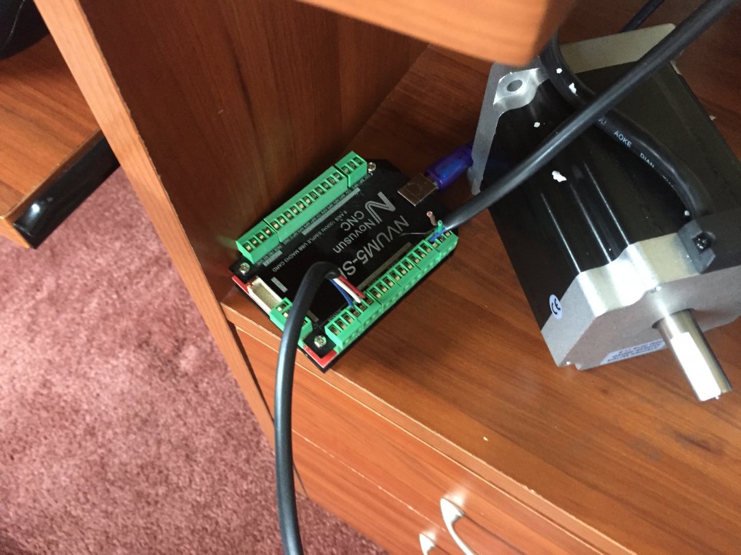
We are running all of this with Mach 3, installed in windows (set up on a mac desktop - yes; a little weird i know). You may notice that this is not using serial connector; it is USB linked. The breakout board/motion controller here was a cheapee china board (like 75 bucks). We are having a problem though.
While we have the motors turning; and they are turning the correct number of programmed turns, the feedrate does not match what we see. It neither matches the actual observable rate we witness on the motors, or the FRO listed on Mach 3 as the motors are turning. We have looked all over in Mach 3 but can't find anything that seems to be set wrong which might affect this. Since neither of us do this for a living, it is difficult for us to determine where we've gone wrong here.
Ill post a video of me running mach 3 so you can see what I'm seeing. Any ideas on why our feed rate doesnt match up? Anyone? Anyone? Bueller?
-JP
Updated 3-9-17
So, things are moving along steadily. We have ordered most of our control related items. I'd say we have maybe 8/10 of everything material and component wise. We did decide to go with an air cooled VFD spindle instead of the water cooled one I went for originally, and 1207 oz in motors as opposed to the 700 ones (same size mounting though) so I'll need to to do a little redesign on my spindle details this weekend.
Dad and I should be able to start cutting some of the machined pieces this weekend as well (though much has been laser cut already).
This process has been a lot of fun. I'm excited to start putting the table together within a week or two here.
-JP
Updated 2-21-17
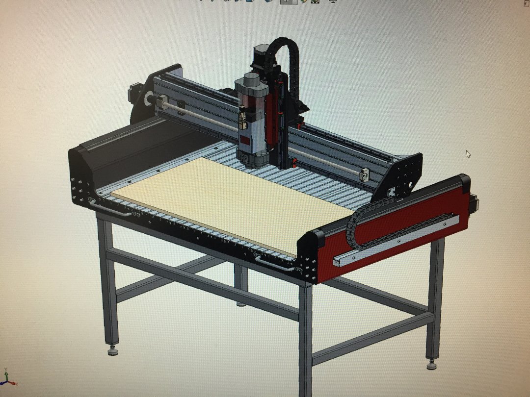
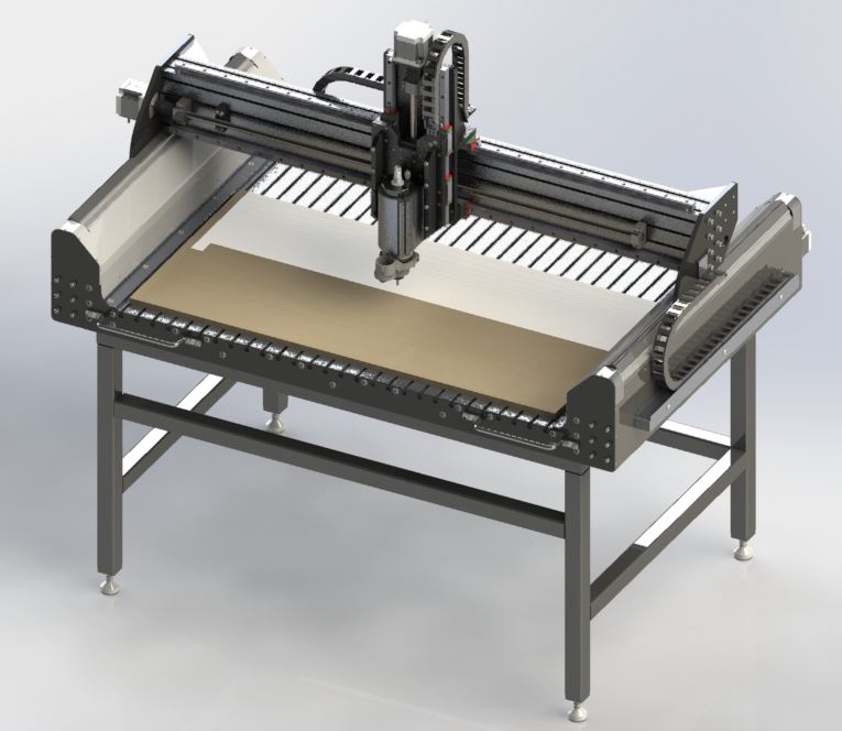
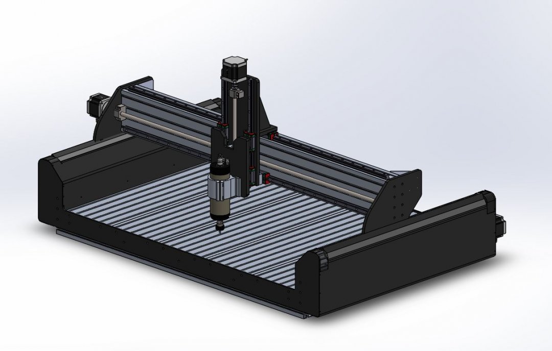
Stage 1 design is complete. Here is the router:
It's been almost a month since my last update. It takes a while to flesh out details on things like this.
My father and I are hoping to start building within a couple months here.
I think we will be at the high side of our budget for this build (close to $7k - and that's only because we are able to do a lot of the machining ourselves), but we are happy with the design.
We have our ball screw assemblies already. We just received our hiwin rail assemblies the other day (they looked great). My ext. alum. stuff is being quoted right now and most of the other make details on here will be water jetted (i have these out for quote).
The base will be a big mamma jamma to do; but we have access to fab equipment and a boring mill - so we will be doing this ourselves as well.
There is no way I could do this thing within budget if i did not have a bunch of family and friends who machine things for a living. I'm very thankful for that!
-JP
Updated 1-29-17
So my dad received the ball screw assemblies on Friday. Everything was good for the Ys but we had issues getting the ballnuts to go on X and Z ball screws. Froze up on both. I am not sure what the 'anti-backlash' mechanism is in these screws, but might have something to do with that? I will read up on it.
CAD-wise here is where I'm at:
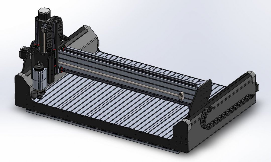
I changed all motors to NEMA 34 640 oz-in. I added cable-carriers (I might remove these for Y and Z though....not sure yet).
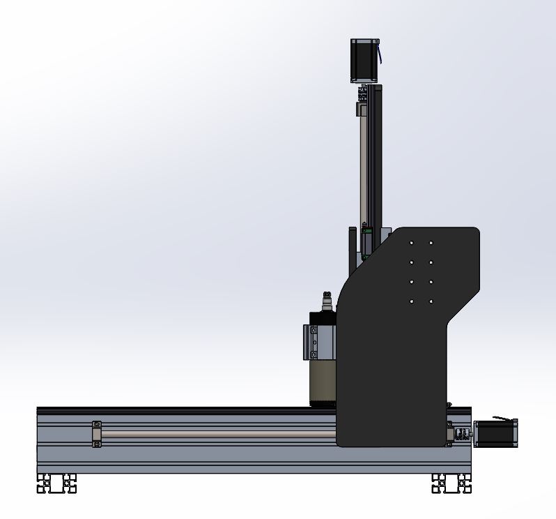
My Z-clearance from gantry to table is about 8". Still kind of high, but I'm considering lowering it some more. I don't know....this seems like it will be solid, but hard to know without building.
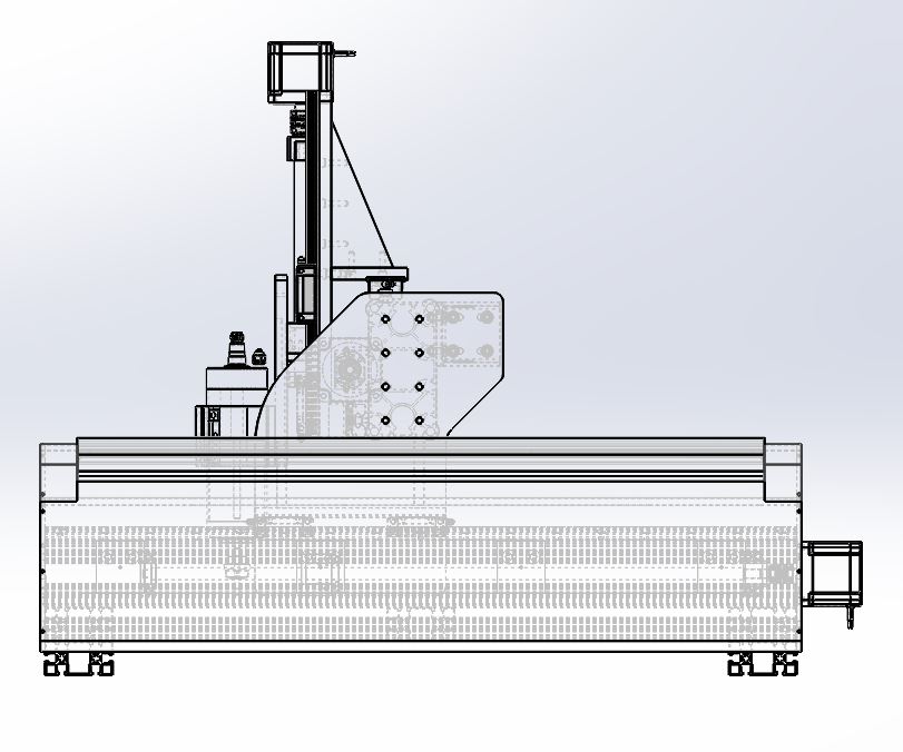
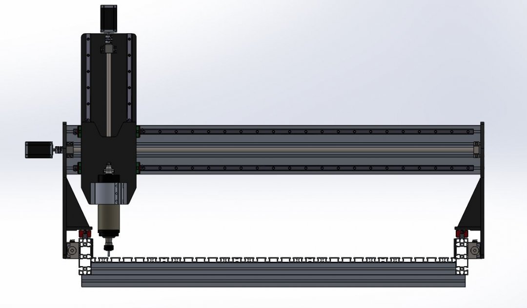
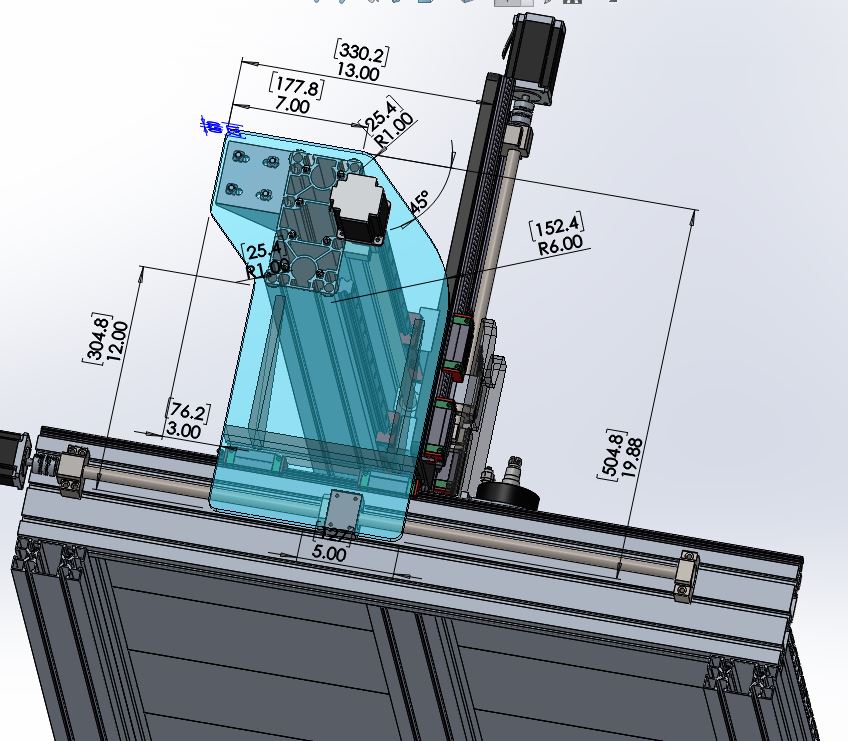
I tried to make my spindle as rigid as possible to compensate for the 8" travel/gantry-height clearance:
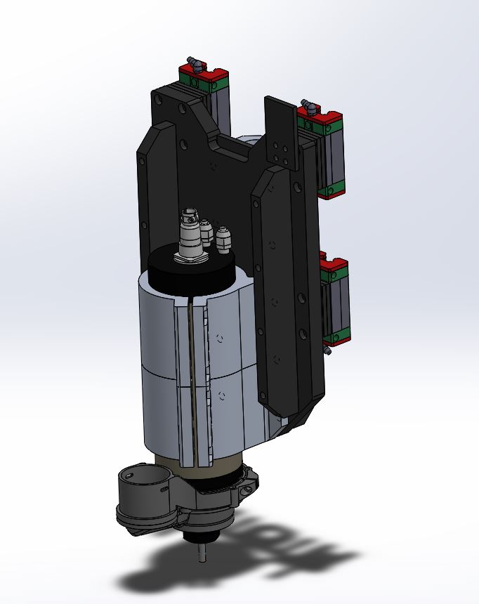
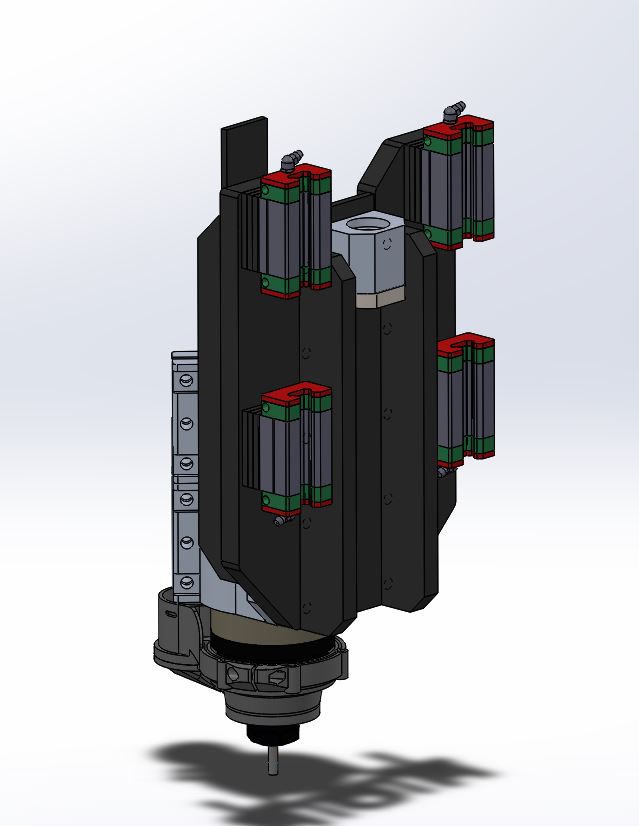
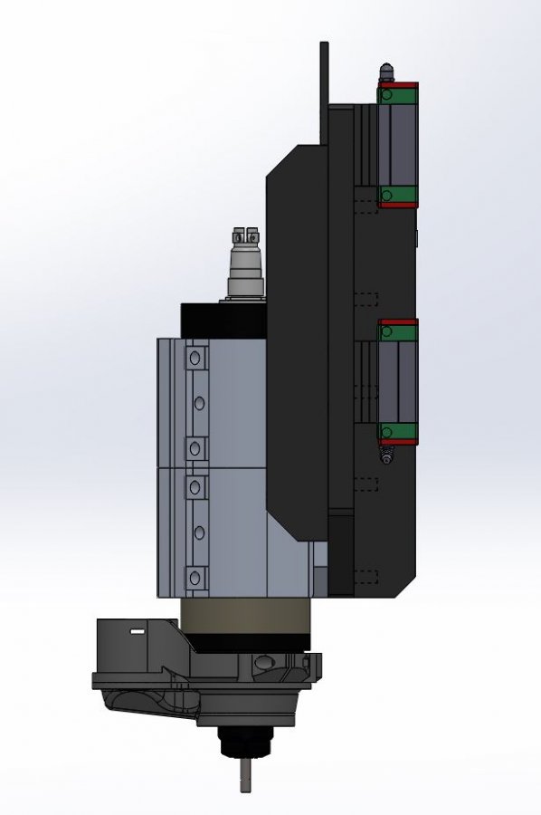
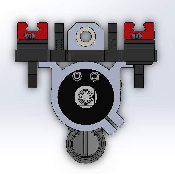
I use 5/8" x 8" x 12" alum tooling plate for the spindle plate; with 1/2" x 1-1/2" bolt-in gussets along the front and back to strengthen it up. I also added an extra spindle bracket to try to distribute some of the load higher up (closer to my bearing blocks). I would move the blocks down; but that would pretty much get rid of my 8" gantry clearance (since my rails would need to move down as well).
Dust-shoe for vacuum shown here was made my Dez on Grabcad (GrabCAD - CAD library). I liked their design because it was low profile. I will probably just try to alter this a bit for my spindle and print these pieces out instead of ordering one. But not a major issue right now; just have it stirring in my mind for later.
Now time for....
--------QUESTIONS/CONCERNS--------
1. (to anyone) Is my Z-height still too much? Should I shorten a couple inches yet? This seems like it will be strong enough; but I know it would still be better to get my spindle loading back over the hiwin bearing blocks a bit more. I think the gusseting and double bracket will help a lot though; seems like enough anyway; but I'm open to constructive criticism.
2. Capacity of my 640 oz-in Z motor. Ok...so I'm not an ME. I'm a middle aged husband/dad with limited amounts of time and a schedule jam packed with everything from work to poopy diapers to this (in my free moments). I would love to go to school; but for me it isn't an option, so I'll do my best to learn as I go. That said I want to know my motor for lifting and lowering the weight hanging on my Z carriage (which is about 30lbs) is going to be plenty beefy enough; so the way I think about motor strength may be primitive; but it goes like this:
- Pi x Dia = circumference
- circumference of a 1" circle is about 6.28".
- linear travel for a 5mm pitch ballscrew is 5mm; or about .197".
- For every 6.28" of radial travel, I get .197" of linear travel. That's about a 30:1 ratio.
- 640 oz-in is about 40 in-lbs.
-I'm pretty sure someone smart like Archimedes or whoever pointed out the relationship between force and distance
-If I don't consider any other forces here (like friction), then theoretically 40 in-lbs pushing radially for a distance of 6.28" to move something linearly a distance of .197" means I have to make about 30 rotations; so I should be able to dead lift something 30x40lbs = 1200lbs of weight (again - excluding all other forces like friction).
Am I thinking about this right? Is my motor going to be that buff?
3. Limit switches. So I am starting to think about these. Anyone have recommendations for what to use? Toggle or inductive?
4. Hard stops. Do I need them? I know I can set travel limit in my software; plus limit switches; so do I need hardstops? Seems like it would be good to have them in case a limit switch failed.
5. Anti-backlash ball screws. I need to machine the one for my Z axis down some. This means I will have to take the nut off the screw and it put it back on later. Has anyone else had issues re-assembling a 16mm, 5mm pitch anti backlash ball nut to the screw?
Thanks and Best Regards to all
-JP
Updated 1-24-17
Thanks to all those on my discussions page for the good advice (as well as some friends, family and coworkers). Design is proceeding along well. My ballscrews would've arrived from FedEx today except no one was home to sign for them; so they should be here tomorrow (first set of parts). I will have to alter my z ballscrew (shorten it) unless they let me return-exchange it. So....hopefully that's an option X-)
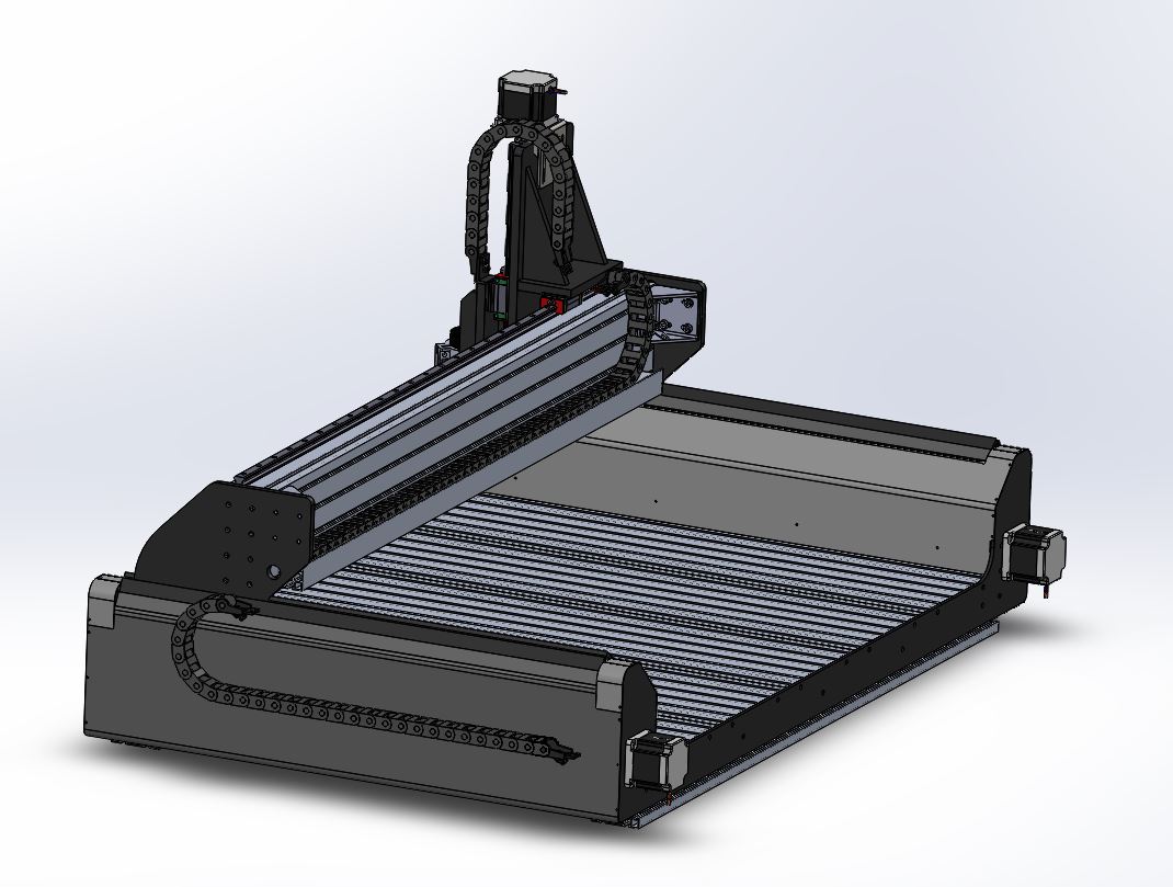
So; since my initial post, I have dropped my Z travel to 8". I was originally shooting for more height to give me clearance for a rotary actuator; but I thought of a workaround which will still let me mount the off the edge and still cut round workpieces at 8" dia. or less.
I have also moved up to NEMA 34 640 oz-in motors across the board.
More details to come later; but for now here are some updated pictures -
Original Post 1-21-17
So I have decided to build a cnc router.
Some background first: I am a machine designer from MI (Solidworks nerd). My father is a machine shop foreman. Both of us have a goodly amount of mechanical knowledge. The electronics side; so-so. It will be a learning experience there.
We know roughly what we want to build and have started our concept phase. We have a zillion questions though – certainly on the controls side of things; I will wait before I get into questioning; but we want to work out something mechanically beefy first and need some advice from veteran cnc router builders. That said – let me lay down some of my model pics and start going through my design scope. Any advice from veterans here will be much appreciated (I list a few of my questions and concerns further down:
--------OVERVIEW--------
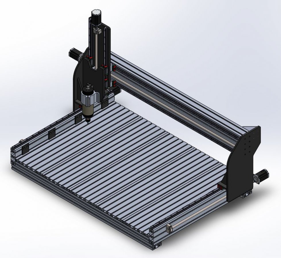
So this is it. It probably looks pricey (and it probably will be reasonably pricey once all done). We have budgeted about $5k-$7k to put into this. So we want it to be super sweet.
The goal is to make something extra rigid for fine quality relief carving hard wood, for profile cutting stuff, for cutting of some ¼” ish size aluminum from time to time and - if I can – for cutting thin steel on rare occasion (but the last one isn’t really on my agenda – so its not necessary).
We wanted something with 2’ front-back (y) travel, 4’ l-r (x) travel and 1’ (if possible) z travel. I realize the gantry goes the length way here and not the width as is typically seen in most cnc routers this size. It was our purpose to try it this way. We wanted something that was both small enough to disassemble and transport and yet capable of carving something as large and long as a door (which – in this case could be perhaps be carved in portions using a pinned subplate fixture mounted to the table; though I realize you’d need to get your travels straight so things blended smoothly when you shifted such a subplate fixture).
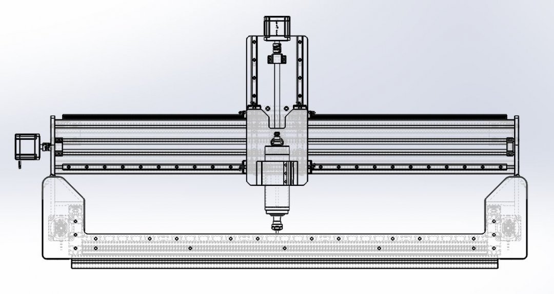
The height on this machine is also pretty tall. I am ok shortening the z travel some, but if I can keep it rigid enough I want the full 1’ travel height for the possible addition of a table mounted rotary axis later on. There is currently 12.13” clearance from the table top to the bottom of the gantry right now. The bottom of the collet is at 1” from the table top in full down travel; so (theoretically) I could use the entirety of space between the table and the gantry for carving whatever I wanted (up to 1’ thick. Chances are I will never need that much unless I did mount a rotary axis (and eventually that’s the idea).
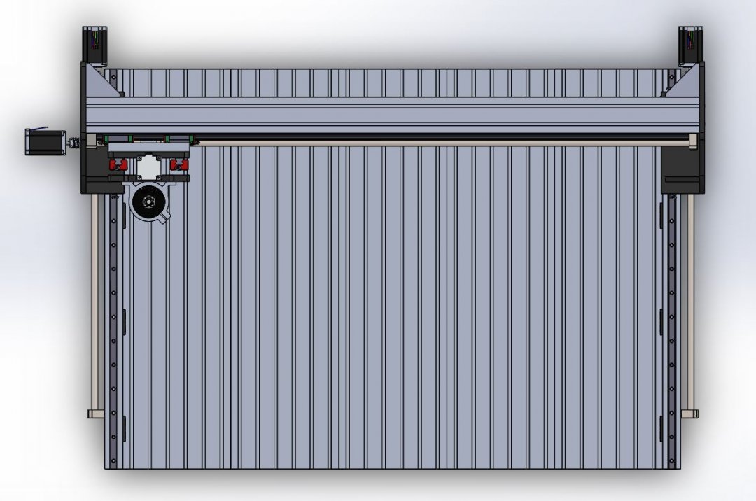
Gantry width shown here is about 60” (1540mm). I have a piece of minitec extrusion (90mm by 180mm profile) with 8 m8 bolts in each end (plus brackets on the backside as you’ll see in other pics). Depth of the table front to back (the pic above would be considered an operator front view) is 1000mm (39.4”).
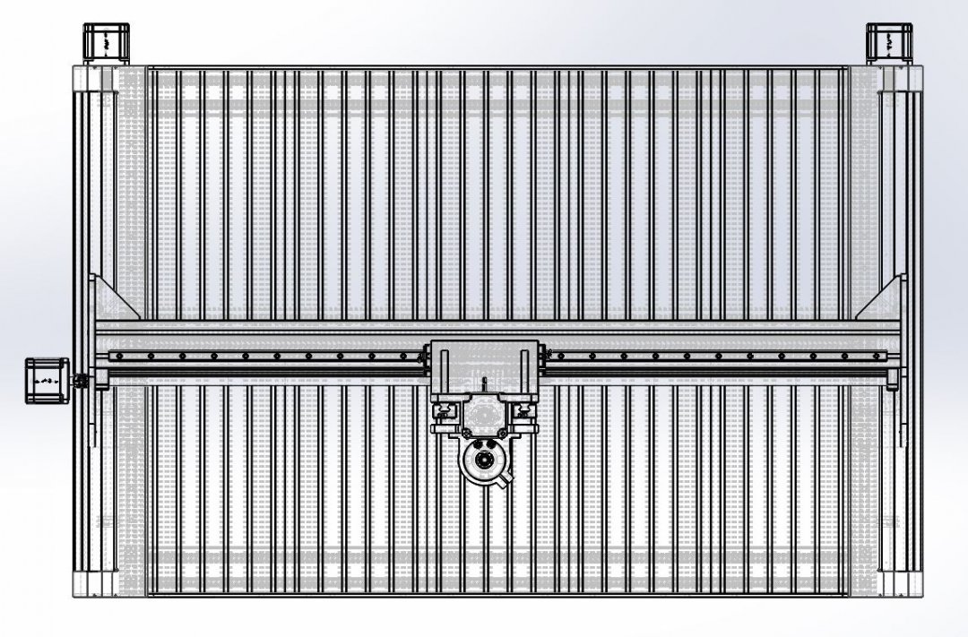
Total weight of everything as shown was like 400lbs I think when I last checked. I think the ext alum table by itself is about 120lbs; maybe 180lbs with motors and bearings and everything (not including gantry brackets and above).
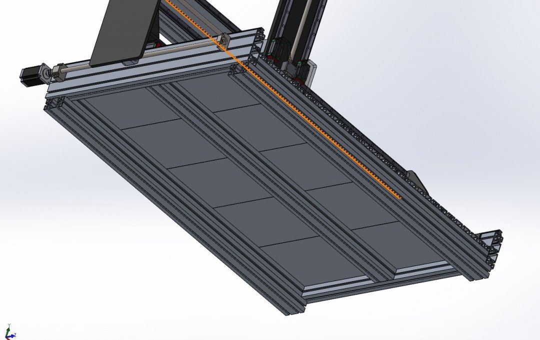
Table is a box frame of 45mmx90mm alum extrusions with an added extrusion across the center for stability. On the top of the box frame ive lined 5 pieces of minitec 19mm x 270 extrusions with t-slots (on top side only) for toe-clamping whatever down. Beneath there are two other cross pieces of 45x90 for ‘feet’ if you will; to rest on and lag to a table I suppose. I don’t show it here but the front and rear ends will have 1/4 “ steel plate across bolting into the alum profiles to make the whole construction nice and rigid.
Right now Ive got nema 23s (420in-oz) everywhere (for 2 y-axes, 1 x axis and 1 z axis). I have (unfortunately) jumped in and ordered my ball screw assemblies already here (only thing I have ordered so far though): 16mm rolled anti-backlash ball screws with the ball nut and end blocks as shown here (10 pitch screw) - 2 screw assemblies for y travel; 1 for x and 1 for z (for example - 2 of these for the y travel - http://www.automation4less.com/store/proddetail.asp?prod=RM1610-0850-0700-FS ).
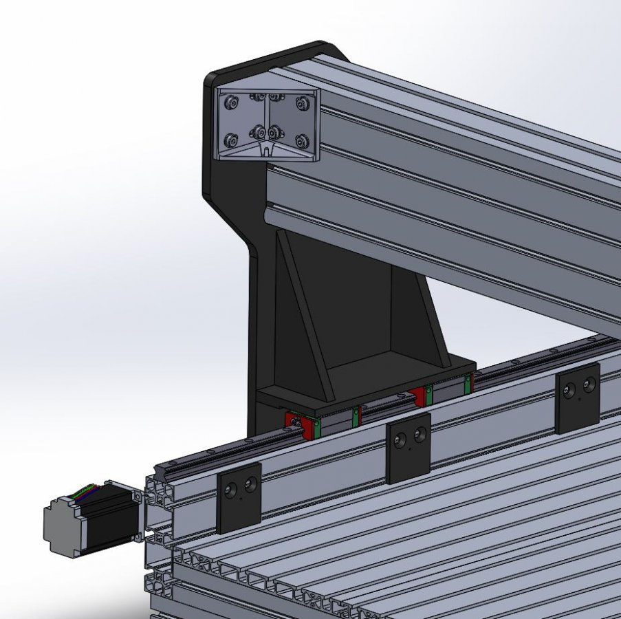
My gantry support brackets look like this:
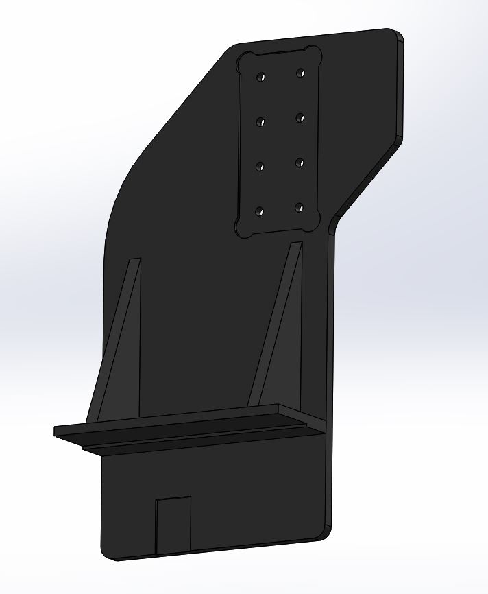
These will be steel weldments (1/2” thick stk.). Ill cut a pocket & holes for my gantry beam, finish a pocket for my ballnut housing (holes not shown yet to mount this) and side cut the linear block mounting face, then put the bracket on a horizontal machine and pop holes in to mount to linear blocks (or maybe just drill em by hand; I can prob get close enough). The wing off the back side will be for an extra gusseting bracket to help stabilize the gantry beam…cuz its loooong. So these brackets are pretty good size and should be strong:
Height is pretty tall right now; and gives me some concern about the rigidity of the z-axis at far travel back/forward, but I have some ideas that I think will tighten that up a lot.
As for limit switches or dust protection or cable carriers - and some of the other things I don’t yet show; these are still to come but will be added.
So that’s it.
--------QUESTIONS/CONCERNS--------
Now for concerns/questions:
1. Is the quality of my spindle cut going to suffer because of vibration in the long gantry beam?
This LOOKS strong to me what with the steel brackets and large alum profile size and all; but I had a friend mention vibration from the cutter throughout the beam as a potential issue. I added the additional back-wing bracket to help prevent some of that (if it’s truly an issue), but is it enough? Will it really be an issue or no?
2. Racking on my y-travel? So because the spread on the gantry brackets is so large, im wondering about racking…I have 2 motors driving ball screws on each side of the Y. I mean; plenty of 4’ wide gantry machines have been made for 8’ long machines, so I THINK this will be good; but then ive never built one of these so I just don’t know. Any ideas? (the pic above with dims gives an idea on the spread of my linear blocks)
3. Ballscrews. Well the lame thing about ordering something before you’ve finished your design is you’re kind of stuck with it. However, if I’ve undersized these screws, Im not opposed to setting my 16mm ball screws aside and going up to 20s. I just want to know these are going to work well. 2 of them will be moving about 230lbs of weight back and forth and that makes me wonder how accurate they will stay over time.
4. Motors; 2 nema 23s 420in-oz to move the 230lbs back and forth. Is this enough? Or will I be stressing these things? I can go up to Nema 34s (and I kind of want to); but IF I do I just want to know that the 16mm ball screws won’t be undersized for Nema 34 motors.
5. My Z travel – so is this “12” of travel” plan just shooting for too much? Will my design suffer in some way as a result? I know it's tall. It seems rather tall compared to the LxWxH Ratios ive seen on other 4' wide cncs. I know there a reason they try to keep the gantry down lower - more rigidity (center of mass moves closer to your bearing support blocks) but this seems beefy enough to me...it seems that way anyway; but if it's going to cost me big money to learn the hard way, i'd rather not. So on height? Think I might be ok here? Be brutally honest! : ]
6. Controls – Open loop or closed loop on the motors? What do I need to drive 2 Y motors, 1 X motor, 1 Z motor; 1 2.2kw water cooled Spindle with VFD, and the possible future addition of a rotary axis? Any help in this area is welcome. I’m just reading a lot right now to try to understand all this; but it’d be seriously helpful for someone with a good understanding of cnc controls to say “hey I think this would work great for your application).
Thanks in advance for any help or constructive criticism!
Kind Regards!
-JP
Warnke CNC Router
Build in 'Cartesian Style CNC' published by JP Warnke, Sep 5, 2017.
A blend of modular aluminum and steel bracketry built to yield fine cuts in hardwood and aluminum. An open table with a shiftable pin-fixture concept will allow the operator to shift longer than Y-travel work-pieces, such as doors, along the Y-axis of the table. This machine has a 44" (X) by 24" (Y) by 8" (Z) travel with water cooled VFD spindle motor, t-slot ext work table, cable carriers, side guards n dual y drives. Total weight (w/base-stand) is about 600lbs.
-
-
Build Author JP Warnke, Find all builds by JP Warnke
-
- Loading...
-
Build Details
- Build License:
-
- CC - Attribution NonCommercial - No Derivs - CC BY NC ND
Reason for this Build
A machining aid for hobby wood work and at home hobby design projects.

