Welcome to Our Community

Some features disabled for guests. Register Today.

Emmett-Delta

Discussion in '3D printers' started by David Bunch, Jan 8, 2016.
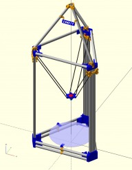
  1. David Bunch

    David Bunch Veteran
    Builder

    Joined:
    Oct 27, 2014
    Messages:
    622
    Likes Received:
    427
    David Bunch published a new build:

    Read more about this build...
     
  2. lolocaledo

    Builder

    Joined:
    May 8, 2015
    Messages:
    13
    Likes Received:
    0
    Hello David,
    Great job and thank you for sharing ...
    Is the tetrahedron at the top necessary ? what is its purpose ?
     
  3. David Bunch

    David Bunch Veteran
    Builder

    Joined:
    Oct 27, 2014
    Messages:
    622
    Likes Received:
    427
    The tetrahedron is not necessary. I just like pyramids & seemed cool to put there. It does add about 20" of height to it in my configuration. If you made a really tall delta printer, it seems like it would make it more stable with the tetrahedron pulling the 3 columns together.

    I added a parametric version of the tetrahedron corners to thingiverse located here: Parametric Tetrahedron Top for Delta 3D Printer by GeoDave
     
    #3 David Bunch, Jan 10, 2016
    Last edited: Jan 10, 2016
  4. David Bunch

    David Bunch Veteran
    Builder

    Joined:
    Oct 27, 2014
    Messages:
    622
    Likes Received:
    427
    On 12/28/15 I ordered 16 Pcs of 10mm OD M4 Threaded Steel Balls ($3.24) & 18pcs N52 Strong Round Magnets D12x5mm Rare Earth Neodymium Magnet with 4mm Hole for $4.12 and received them in the mail this past Saturday 1/9/16. That is the least expensive I have seen them. Here is the link on bangwood for those 2 parts.

    16Pcs Φ10 M4 Threaded Steel Ball Rod Ends For Kossel 3D Printer Magnetic Joints
    18pcs N52 Strong Round Magnets D12x5mm Rare Earth Neodymium Magnet with 4mm Hole

    I also bought 6 carbon fiber arrows from Walmart for $3.25 each. If you decide to buy arrows from walmart, I would suggest getting them this time of year as they seem to be a seasonal item with them. I could not find them in the Spring last year when I was looking for them for another project.

    I had bought some cylinder magnets before, but these discs with the spherical indentation connect to more surface of the balls.

    I am not sure how I will put all this together yet, but am sure some idea or suggestion from others will find the answer. I have been going back & forth whether to use traxxus or magnet connections, but since I found these for such a good price, magnets are probably the way I will go.
     
  5. David Bunch

    David Bunch Veteran
    Builder

    Joined:
    Oct 27, 2014
    Messages:
    622
    Likes Received:
    427
    I made a parametric carriage Base for V-Slot in case someone needs a different size than what I am using. There are 17 variables you can adjust to get it to the way you want it & you can add your own carriage file to the top of the base if you want to use a different carriage. The openscad file is located on thingiverse here:

    Parametric Carriage Base for V-Slot Printers by GeoDave
     
  6. David Bunch

    David Bunch Veteran
    Builder

    Joined:
    Oct 27, 2014
    Messages:
    622
    Likes Received:
    427
    Is there some optimum width between the pairs of Delta Arms? I have not seen where anyone has mentioned this. I was checking some dimenions on mag effectors on thingiverse & saw dimensions of 46,50,54 & one that was over 70mm between the centerlines of the pair of rods. Looks like the Traxxus carriage I was starting with was about 60mm.
     
  7. Atomist

    Atomist New
    Builder

    Joined:
    Aug 7, 2014
    Messages:
    46
    Likes Received:
    11
    Just curious if you considered making a carriage that would ride on EMT as well? I can't imagine that it couldn't work properly. It'd be easy enough to modify one of the carriages from the mpcnc build.
     
  8. David Bunch

    David Bunch Veteran
    Builder

    Joined:
    Oct 27, 2014
    Messages:
    622
    Likes Received:
    427
    I did experiment with that & believe it can be done. Take a look at this idea. V-Wheel carriage between four 1/2" EMT or PVC Pipe by GeoDave
    There was someone on thingiverse that was looking at taking my Emmett design & using EMT vertically as well. Not sure if he made progress on it. I think 1/2" EMT would be a better choice for the vertical , since it would keep Vertex parts from being too big. I started to make a vertex for this configuration, but did not finish it. If you are interested in trying it, I will do a little bit more work on it & post the stl file. I also made a parametric Carriage design that would make it fairly easy to get the right width carriage for it. Parametric Carriage Base for V-Slot Printers by GeoDave
     
  9. Atomist

    Atomist New
    Builder

    Joined:
    Aug 7, 2014
    Messages:
    46
    Likes Received:
    11
    If you want to post the stl, I'd give it a go. Print it, test it, tweak it. I saw your other carriage awhile back. I just think it'd be neat to do a full emt build.
     
  10. David Bunch

    David Bunch Veteran
    Builder

    Joined:
    Oct 27, 2014
    Messages:
    622
    Likes Received:
    427
    I took a look at it for a few minutes tonight & should have something for you to try sometime tomorrow.
     
  11. David Bunch

    David Bunch Veteran
    Builder

    Joined:
    Oct 27, 2014
    Messages:
    622
    Likes Received:
    427
    I created a Top vertex using 4x 1/2" EMT for the Vertical & uploaded the file to the files area & is called VertexTop_1xEMTH_4xEMTV_rev54.zip It took a little longer to create than I thought, so let me know if the top looks ok before I create the Bottom Vertex. Here are 2 screen shots of what it looks like.
    VertexTop_1xEMTH_4xEMTV_InsideView.JPG VertexTop_1xEMTH_4xEMTV_OutsideView.JPG
     
    #11 David Bunch, Feb 1, 2016
    Last edited: Feb 1, 2016
  12. David Bunch

    David Bunch Veteran
    Builder

    Joined:
    Oct 27, 2014
    Messages:
    622
    Likes Received:
    427
    I added the Bottom Vertex for using 4x 1/2" EMT vertically in the files area. It is called VertexBot_2xEMTSH_4xEMTV_rev54.zip
    Here is what it should look like.
    VertexBot_2xEMTSH_4xEMTV_rev54.jpg
     
  13. Cobalt Griffon

    Builder

    Joined:
    Oct 5, 2015
    Messages:
    20
    Likes Received:
    0
    How'd you end up mounting the Duet board to the electrical conduit? I'm working on a build using the electrical conduit towers, and I'm wondering how to mount the electronics to the frame.
     
  14. David Bunch

    David Bunch Veteran
    Builder

    Joined:
    Oct 27, 2014
    Messages:
    622
    Likes Received:
    427
    I put this project aside as it seemed to be too much trouble for me to use EMT for a Delta. I have since built a Folgertech Kossel Mini & may work on another 3d printer this winter. That being said, I took a look at your problem & came up with this possible solution for you. I added a zip file to file area called: EMT_DuetElectBrackets_161010.zip which has 2 openscad files, 2 dxf files & 2 STL files generated from the openscad file. The dxf file is referenced by the openscad file. The dxf file should make it easier to change the brackets if they only need to be adjusted a little.

    I have attached 3 screen captures to give you an idea of how this might work. After I finished these calculations, I forgot about the motor being attached there, so the brackets might have to lengthen some if that is in the way. Currently the Duet board should be 29.5mm from where the motor mounts on the plastic vertex. To get 49.5mm instead of 29.5mm, the tabs would have to extend another 10mm each. Since you are using EMT vertically, I assumed the vertex showed in the 2D drawing is what you are using. The idea of this bracket is similar to the glass holding bracket. I got the dimensions & hole spacings of the Duet board from: Duet - RepRapWiki

    This is of course is untested, so you have to determine whether this will work. Here are 3 photos of the idea. The 2d assembly image, 1st brackets centerline is 75.24mm from end of the EMT & 2nd brackets centerline is 79.67mm from 1st bracket centerline. The dimensions of the Duet board I used are also shown. If the brackets need to be extended by 10mm, that distance from the end of the EMT measures an additional 17.3mm. Let me know how it goes. When you get your machine put together, I would like to see some photos of it.
    EMT_ElectronicsBracketAssembly_rev9.jpg EMT_ElectronicsLongBracket_rev9.jpg EMT_ElectronicsShortBracket_rev9.jpg
     
  15. Cobalt Griffon

    Builder

    Joined:
    Oct 5, 2015
    Messages:
    20
    Likes Received:
    0
    Thanks David,
    I'm using exactly the brackets you assumed, their absolute monsters to print, took my Mini Kossel about 13 hours for each of the lower corners and 6.5 hours for each of the uppers. I'm still waiting on delivery of my Duet 0.8.5, but the basic dimensions you've got look good. I'll post some pictures once I've got things assembled. I'm building around the idea of using the new Prometheus System from DisTech for the hot-end, frame lengths are 42 cm for the horizontals, and 152.4 cm for the towers.
    Thanks,
    Edward Simpson
    Cobalt Griffonary
     
  16. David Bunch

    David Bunch Veteran
    Builder

    Joined:
    Oct 27, 2014
    Messages:
    622
    Likes Received:
    427
    I know what you mean about printing those vertex parts. I can not tell you how many different versions I printed before getting them close enough.

    After I did that electronic board mounting design, I thought it might be easier to mount it on the side & should be simpler to assemble & you can put it anywhere along any side. I created these 8mm thick but the other ones were 12mm. Change the variable S_Ht to the height you want in the openscad file. I have an option in the openscad file for you to see how it looks connected to the EMT & vertex. Just set Assemby variable to 1. There are at least a couple of other variations that could be done with this design.
    1. change the support to underneath instead of above, but mounting holes might be a problem
    2. Could also make Duet board mounting holes on a tab extended above or below the extruded profile.

    I have attached a screen shot of the assembly & a zip file with all the parts. Since you gave me the lengths of your horizontals, I made them that size in the assembly. That is a pretty small electronics board.
    EMT_ElectronicsSideBracket_10.jpg
     

    Attached Files:

  17. Cobalt Griffon

    Builder

    Joined:
    Oct 5, 2015
    Messages:
    20
    Likes Received:
    0
    Thanks for designing that second mount. I'll definitely post some pictures when I've got it assembled :)
    Edward
     
  18. David Bunch

    David Bunch Veteran
    Builder

    Joined:
    Oct 27, 2014
    Messages:
    622
    Likes Received:
    427
    You got me interested in doing some more design on this project. Not sure I will print any of these, but I will further the design. After working on these brackets, I was thinking it would be easier to clamp something to the top horizontal pipes if there were 2 on each side like the bottoms. To keep the same spacing as the bottom, that would increase the height of the top vertices by 24mm. If 1/2" EMT were used for the top horizontals, I could decrease that 24mm by 10.6mm keeping the same gap between the EMT. I could also cut off a little bit of plastic where the 1/2" EMT butts up against the vertex. If you have not printed your top vertices, does that interest you?

    This would allow me to bolt a modified design of this filament holder to the top & also an extruder. This filament holder has worked really well for me.
    Parametric openscad Remix of Universal stand-alone filament spool holder by GeoDave

    How are you mounting the P/S? I could modify this design: Folger Tech Kossel P/S Bracket with slot opening for T-Nut Connection by GeoDave using the similar clamping that the electronics uses.
     
  19. Cobalt Griffon

    Builder

    Joined:
    Oct 5, 2015
    Messages:
    20
    Likes Received:
    0
    Hi David,
    I'm using one of your filament holders on my Mini Kossel already :) and I'm definitely putting a couple on this new beast. I've already printed my top corners to you original design, but the idea is definitely a good one. Personally, I was thinking of having the spools mounted on top of the upper corners, should provide a solid base to mount them to, that or I might put them vertically on arms that extend from the side? As for the P/S, I'm using this one (24V DC 15A 360W Regulated Switching Power Supply) and I was thinking of mounting it under the heat bed beside the duet. There's definitely enough space there with a 30cm print-bed :) On the extruders, the ones I'll be using are based on planetary geared NEMA 17s, so a simple clamp to hang them from the top should work just fine :)
    I'll be doing the frame assembly later today, so I'll post some pictures when it's together.
    Edward
     
  20. David Bunch

    David Bunch Veteran
    Builder

    Joined:
    Oct 27, 2014
    Messages:
    622
    Likes Received:
    427
    Mounting the spools on the corners should work. I have had one mounted on the top end of v-slot 2020 on my Makerfarm i3v 10" for almost 2 years without any problems with it. I was reading a little about the duet on their site & they recommend having a cooling fan if you mount it horizontally. Are you going to have some cooling under the print bed, especially if you are putting the P/S under there? Are you going to be using a heatbed on that machine?

    I redid the Duet mount slightly to use 4.5mm holes since the duet is sized for M4 screws. You might want to change Mnt_Hole_ID=4.5 variable in the openscad file & make it a couple of mm's thicker. I will upload that change later to the files area, but that is all I changed. I found more detail info on that board here. Mounting and cooling the board - DuetWifi Wiki

    -David
     
  21. Cobalt Griffon

    Builder

    Joined:
    Oct 5, 2015
    Messages:
    20
    Likes Received:
    0
    I'm definitely putting a couple of cooling fans under the bed, I think a pair of 5010 or 6010 case fans should provide plenty of cooling. As for the bed, it's one of Ultibots 30cm heatbed kits, and I'm planning to use a couple of these Pyron mats for insulation. I'm currently using one 5010 fan to keep the ramps 1.4 that powers my mini Kossel cool and it's under the heat-bed with one of those mats for insulation, it's been run up to 17 hours at a time without any overheating issues at all.
    Edward
     
  22. David Bunch

    David Bunch Veteran
    Builder

    Joined:
    Oct 27, 2014
    Messages:
    622
    Likes Received:
    427
    What are you using for Sliders/Carriages? I have a couple of different customizable designs I can add here. One is based on this modified design of the Folger Tech Slider/Carriage. Folger Tech Sliders and Carriage Remix V2 by GeoDave The other is a customizable version of Jerry's Design in the Delta-Six build. That gives you 2 different options for arm spacing also. I do not have one for a magnetic arm if you are using that, but something like this adapter could be modified to use magnetic arms. Cerberus Carriage Adapter for Magnetic Arms by blah_59

    What type of wheels are you using, one of the V-slot wheels or a nylon wheel like this one: Nylon Roller Wheel (used on Rev B kossel) ?
     
    #22 David Bunch, Oct 12, 2016
    Last edited: Oct 12, 2016
  23. Cobalt Griffon

    Builder

    Joined:
    Oct 5, 2015
    Messages:
    20
    Likes Received:
    0
    I'm using Traxxas 5347 joints for my rod arms, and I've got 12 Solid V-wheels for the carriages. As to what style of carriage, I was planning to retune your Folger tech remix for the EMT towers. As for the arm spacing, I'm thinking that wider is probably better in this case, so I'll probably use something around 5-6 cm. And as for the effector, I'm planning to design something custom, probably starting from the Kossel source files.
    Edward
     
  24. David Bunch

    David Bunch Veteran
    Builder

    Joined:
    Oct 27, 2014
    Messages:
    622
    Likes Received:
    427
    That is perfect as that is the slider I was working on making customizable. I did a couple of test prints using the nylon wheels I got from Folger Tech as a test & seems to work good. You can adjust the hole pattern for the carriage to what you are using. It is currently set to a 20x20mm hole pattern for the carriage. I have some V-Slot Wheels & might print a version for that tonight. I will upload this to thingiverse tomorrow as more people might find it there. I made the Wheel spacers a separate part, so they can be fine tuned for the proper height without having to reprint the sliders. The openscad file gives a good indication of how those wheels will fit in the assembly, but might take a couple of test prints to get the best fit. Here are a couple of screens shots & a photo of the part attached to 4 1/2" EMT. I used M5x35mm screws for the wheels. You could also make a blank slider for the opposite side which might give a smoother motion since it such a large offset from the carriage, but the screws would probably have to be 60mm long.
    EMT_CustomizableSlider.JPG EMT_CustomizableSlider_V_SlotWheelSideView.JPG EMT_CustomizableSlider_NylonWheelSideView.JPG IMG_1489_800x600.jpg
     
  25. David Bunch

    David Bunch Veteran
    Builder

    Joined:
    Oct 27, 2014
    Messages:
    622
    Likes Received:
    427
    Here is the customizable slider on thingiverse: Customizable Delta Sliders for use with 1/2" EMT Verticals by GeoDave . It works better than I thought it would. After Allted commented that these 4x EMTs might pull apart, I was wondering if those pipes might need to be glued or jbwelded together as they can be pulled apart, but as the slider goes over them, they do stay together. Thanks for inspiring me to work on this project again.

    -David
     
    #25 David Bunch, Oct 13, 2016
    Last edited: Oct 13, 2016
  26. David Bunch

    David Bunch Veteran
    Builder

    Joined:
    Oct 27, 2014
    Messages:
    622
    Likes Received:
    427
    I have been working on making the parts to use 1/2" EMT for the Horizontal & Verticals & assembling the parts in openscad to see what problems show up. I have cut down the amount of plastic a good bit using 1/2" EMT instead of the 3/4", changing the profiles at the corners & cutting more holes. Seems like it should be just as strong with those holes cut.

    The cubic centimeter volume for the bottom vertex went from 249 to 140.
    and the top vertex went from 131 to 119.

    I am sizing this build for the 300mm heat bed by seemecnc & the height is at 1 meter. The horizontal 1/2" EMT lengths come out to 344mm with the heat bed mounting holes centered on the pipe.

    I have not printed any of these yet, but will ponder the design a little more before doing that or posting the files.
    Here is what it looks like so far.
    Emmett-Delta_18mmEMT.jpg
     
  27. Cobalt Griffon

    Builder

    Joined:
    Oct 5, 2015
    Messages:
    20
    Likes Received:
    0
    Looks pretty good, I'm currently about half-way through assembling the main frame. Here's a couple of pictures:
    IMG_20161013_202739487 (2).jpg
    IMG_20161014_124123534 (2).jpg
    Edward
     
  28. David Bunch

    David Bunch Veteran
    Builder

    Joined:
    Oct 27, 2014
    Messages:
    622
    Likes Received:
    427
    That is going to be a really colorful Delta. You are coming right along. I like your different colors for the X, Y & Z towers. Have you tested putting your verticals together yet? I have a test set of 4 1000mm lengths clamped together at each end with about 1/2" plastic clamp & I am seeing about 1mm gap between the pipes about half way between the EMT along where the wheels roll. I am wondering if it would be good idea to put a little epoxy between these pipes. Making sure the epoxy does not hit the metal where the wheels ride would be the main thing to watch out for when gluing these

    I did a google search to see which glues would work best & came across this interesting video that tested several different epoxy brands. From this video the Loctite Epoxy Metal / Concrete looks the strongest.

    Loctite Epoxy Metal / Concrete from Loctite Adhesives

    I am not sure of the best procedure to glue this, but maybe gluing 2 pipes together at a time resting on something like this while you glue them, then when putting all 4 together clamping them with 2 of these. I included the openscad file I used here along with a STL file
    EMT_2x18mm_GlueJigBracket_Rev3.jpg
     

    Attached Files:

  29. Cobalt Griffon

    Builder

    Joined:
    Oct 5, 2015
    Messages:
    20
    Likes Received:
    0
    I haven't test assembled the verticals yet, but if you're seeing 1mm flex over a 1 meter length, then I should probably add some interconnects to my towers. Two things that came to mind when I was looking at the cross section for gluing is that it'd probably be a lot stronger to make some spacers that fit in the central void and glue to those, rather than running epoxy along the tangent points, that or you could just sink some screws through the diagonals from the outside as long as you aren't using a back-plate on the carriages.
     
  30. David Bunch

    David Bunch Veteran
    Builder

    Joined:
    Oct 27, 2014
    Messages:
    622
    Likes Received:
    427
    I was initially looking at something like this which I think is what you are talking about, but thought the other way might be easier. I made this design so it is 5% smaller the area between the pipes to make sure the pipes still fit against each other.
    EMT_4x18mmEMT_GlueSpacer.jpg
     

    Attached Files:

Share This Page

  1. This site uses cookies to help personalise content, tailor your experience and to keep you logged in if you register.
    By continuing to use this site, you are consenting to our use of cookies.
    Dismiss Notice